- 1. Summary
- 2. Introduction
- 3. Architecture
- 4. Scratch remote sensor protocol
- 5. Configuration
- 6. Adapter Types
-
- 6.1. GPIO Adapter
-
- 6.1.1. GPIO Adapter, input
- 6.1.2. GPIO Adapter, output
- 6.1.3. GPIO Adapter, output for PWM controlled Motor
- 6.1.4. GPIO Adapter, output for Servo motors
- 6.1.5. GPIO Adapter, output for Stepper motors
- 6.1.6. GPIO Adapter, various Adapters using multiple GPIO
- 6.1.7. Telephone Dial Plate Adapter
- 6.1.8. GPIO HCSR04 connected with one wire
- 6.2. SPI based Adaper
- 6.3. I2C-Adapters
- 6.4. GPIO Wire adapter, w1-gpio
- 6.5. Remote Communications
- 6.6. Scratch related Adapters
- 6.7. Operation System Adapters
- 6.8. Adapters for special purpose Devices
-
- 6.8.1. Atmel atmega328 with custom firmware as ADC
- 6.8.2. Atmel atmega328 with custom firmware as frequency counter
- 6.8.3. Atmel atmega328 with custom firmware for DHT22, DHT11
- 6.8.4. Test Adapter
- 6.8.5. Servoblaster
- 6.8.6. Raspberry Pi DMA Adapter RPIO2
- 6.8.7. Raspberry Pi SenseHat
- 6.8.8. Pimoroni PianoHat
- 6.8.9. Smartphone positional sensor for scratch
- 6.8.10. USB barcode scanner
- 6.8.11. USB blink(1)
- 6.8.12. Adapter for SIM800 GSM Modem, SMS support
- 6.8.13. RFID Adapter
- 6.8.14. ScratchBoard, PicoBoard Adapter
- 6.8.15. Arduino UNO Adapter
-
- 6.8.15.1. Step 1, program the firmware to arduino UNO
- 6.8.15.2. Step 2, Sample hardware setup.
- 6.8.15.3. Step 3, connect arduino with USB-Line to RaspberryPi or windows computer.
- 6.8.15.4. Step 4, start scratchClient with configuration
- 6.8.15.5. Step 5, start scratch with sample program
- 6.8.15.6. Configuration Tool
- 6.8.15.7. Constraints
- 6.8.15.8. Advanced Features
- 6.8.15.9. Configuration Remarks
- 6.8.16. Arduino UNO Adapter for Neopixel
- 6.8.17. Arduino UNO_POWERFUNCTIONS_Adapter
-
- 6.8.17.1. Step 1, program the firmware to arduino UNO
- 6.8.17.2. Step 2, Hardware setup.
- 6.8.17.3. Step 3, connect arduino with USB-Line to RaspberryPi or windows computer.
- 6.8.17.4. Step 4, start scratchClient with configuration
- 6.8.17.5. Step 5, start scratch and create scratch Program
- 6.8.17.6. Constraints
- 6.8.18. Twitter_Adapter
- 6.8.19. Openweathermap_Adapter
- 6.8.20. LEGO WeDo 2.0 Adapter
-
- 6.8.20.1. Hub features
- 6.8.20.2. Motor Features
- 6.8.20.3. Motion sensor Features
- 6.8.20.4. Tilt Sensor Features
- 6.8.20.5. Installation
- 6.8.20.6. Connection Options
- 6.8.20.7. Connection Sequence
- 6.8.20.8. Basic setup
- 6.8.20.9. Advanced setup
- 6.8.20.10. Complete setup
- 6.8.20.11. Sample scratch Program
- 6.8.20.12. Remarks
- 6.9. Adapters using pigpiod-Daemon
- 6.10. Pimoroni MICRO DOT PHAT board
- 6.11. Pimoroni SCROLL PHAT HD board
- 6.12. Minecraft on PI adapter
- 7. Configurations for Devices
- 8. GUI, Web Interface for Monitoring
- 9. Installation, Operation
- 10. Extending Functionality
- 11. Adapter Documentation
-
- 11.1. ADC_ADS1015_Input
- 11.2. ADC_DAC_PCF8591
- 11.3. ADC_MCP3008_10_Input
- 11.4. ADC_MCP3202_10_Input
- 11.5. ADC_MCP3202_10_Zone_Input
- 11.6. ADC_MCP3202_12_Input
- 11.7. BipolarStepper
- 11.8. Blink_Adapter
- 11.9. CAP1208Adapter
- 11.10. CommunicationAdapter
- 11.11. DMA_PWM
- 11.12. DMA_PWM_ON_OFF
- 11.13. DMA_PWMServo
- 11.14. Festival_Adapter
- 11.15. Gpio_HCSR04_OnePin_Input
- 11.16. Gpio7segment
- 11.17. GpioButtonInput
- 11.18. GPIODialPlateEncoder
- 11.19. GPIOEncoder
- 11.20. GpioEventInput
- 11.21. GpioInput
- 11.22. GpioOutput
- 11.23. GpioOutputPWM
- 11.24. GpioOutputPWM_ON_OFF
- 11.25. GpioOutputPWMServo
- 11.26. GpioStateOutput
- 11.27. GpioValueInput
- 11.28. GpioValueOutput
- 11.29. HC_SR04_Adapter
- 11.30. HIDScanner_Adapter
- 11.31. IRDistanceInput
- 11.32. Linux_Adapter
- 11.33. Linux_APLAY_Adapter
- 11.34. Linux_ARECORD_Adapter
- 11.35. Linux_ASR_Adapter
- 11.36. LIRC_Adapter
- 11.37. Luminosity_BH1750_Input
- 11.38. MAX31855_Adapter
- 11.39. MCP23S17_Adapter
- 11.40. Microdot_Adapter
- 11.41. MinecraftAdapter
- 11.42. MQTT_Adapter
- 11.43. NEOPIXEL_Adapter
- 11.44. Openweathermap_Adapter
- 11.45. PianoHat_CAP1188_Adapter
- 11.46. Pico2Wave_Adapter
- 11.47. PicoBoard_Adapter
- 11.48. Pigpiod_DHT11_Adapter
- 11.49. Pigpiod_PWM_Adapter
- 11.50. Pressure_BMP085_Input
- 11.51. PWM_PCA9685
- 11.52. PWM_SN3218
- 11.53. RFID_Reader_Adapter
- 11.54. ScratchStartclickedAdapter
- 11.55. ScrollPhatHd_Adapter
- 11.56. SenseHat_Adapter
- 11.57. ServoBlaster
- 11.58. SonicPi_Adapter
- 11.59. TimeAdapter
- 11.60. Twitter_Adapter
- 11.61. UnipolarStepperModule
- 11.62. UnipolarStepperStep
- 11.63. UNO_Adapter
- 11.64. UNO_POWERFUNCTIONS_Adapter
- 11.65. W1_DS1820
- 11.66. WebsocketXY_Adapter
- 11.67. Wire_SHTx
- 11.68. WS2801_Adapter
- 11.69. Adapter Data Types
- 12. Index
- 13. References
This document describes software connecting scratch to hardware on Raspberry Pi.
The goal is to have a flexible approach where hardware setup is basically configured instead of programmed.
There are ready to use adapters for basic IO capabilities, as buttons, switches, stepper driver, photointerrupters, PWM-driving outputs. SPI based devices are available for ADC, DAC and LED-Stripes.
Functionality is not only limited to hardware IO. Other examples are a Text to Speech interface or remote scratch-to-scratch-connection.
Scratch does not allow direct interfacing to hardware.
For scratch version 1.4, as available on RaspberryPi raspbian, the 'Remote Sensor Protocol' allows to attach external processes which then interface to hardware.
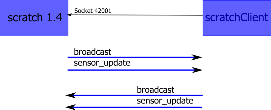
When activated, scratch acts as a server on socket port 42001 and clients can connect to this socket.
The 'Remote Sensor Protocol' is described in /rsp/. It is not limited to sensors, but can also be used for controlling actors, write to files and many more functionalities.
Clients do not need to be located on the same computer with scratch, but could also be remote on a network.
The sensor protocol is generally usable on different computer platforms, and not limited to Raspberry Pi. The Raspberry Pi offers easy to be attached GPIO (general purpose Input Output), which leads to simple and low cost implementations in controlling hardware.
The data exchange are
-
broadcast events from scratch to client. Broadcasts are used for simple commands like 'start' or 'stop'.
-
sensor-updates from scratch to client. Sensor-updates are similar to broadcasts, but carry an additional value.
-
sensor-updates from client to server
-
broadcast events from client to scratch.
Sensor-updates are used to carry additional values like voltage measurements, speed values, or pin state like '0' or '1'.
There are some client implementations available for this protocol. See /simon/ and /silent/, there are many if you search the net.
For an afterschool workschop for 7th class programming novices, I needed a flexible approach to have hardware attached to scratch. The available implementations are either too specialized or lack some flexibility in configuration.
The code provided here is partially based on code from /simon/, which was basically reorganized, modularized and extended.
The implementation has the following goals:
-
Modularization of Software (server connection, data model, configuration, monitoring)
-
Configuration in XML for various adapter-settings; versioning of config files.
-
html based GUI for monitoring and simulation, also providing some documentation on the current configuration.
-
dynamic mapping of broadcast names and variable names to the scratch world
-
internal GPIO-Numbering is BCM style. Configuration allows for BCM, board or other names.
-
Till 2015-01-02, there was a feature to use different GPIO-libraries. This was removed, as RPIO did no longer support Pi2-hardware, and as software was too complex by this feature. A local patch to RPIO, named 'RPIO2', is used instead.
Performance was not a primary goal. If you need to squeeze out a few cpu-cycles, then head for a C++ based implementation.
The scratchClient is designed to run on Raspberry Pi, raspbian. Scratch will in general run on the same machine, although it could run on other platforms too.
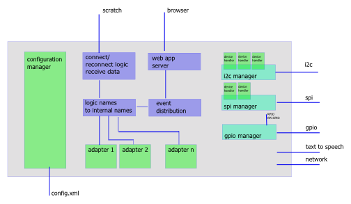
Configuration manager. Reads config file, instantiates adapters and populates the logic to internal names conversion tables.
Logic names to internal names. Scratch is working with 'logic' or business related names. Examples are 'light on', 'distance Y' or 'red button pressed'. These are mapped to internal technical names.
Connect/reconnect logic. Connecting to scratch, reconnecting if needed.
Web app server. Provides view of configuration; monitoring, controlling the adapters.
Event distribution. Scratch signals, signals from/to web app and signals from the adapters need to be distributed between the objects inside the scratchClient.
SpiManager, i2cManager, gpiomanager. These modules manage the access to the Rpi resources; 'device handlers' to handle popular devices.
And adapters. These are the main building blocks, encapsulating the business logic. An adapter is a module, which performs a dedicated operation like a button-adapter, a relais adapter or a stepper.
Scratch applications typically will not use a large number of adapters. My typical applications use up to 10 GPIO pins and one or two adc channels. This yields to 10, possibly 20 adapters involved.
Basically, adapters have a high level command input interface like 'on' or 'off' for a relais, or value inputs like 'direction left/right' or 'speed 2.32' for a stepper control. Adapters can provide value output, as a switch-adapter (state=on/off) does or an AD-Converter. An adapter can use multiple inputs, values and outputs.
Configuration parameters are inputs only used during initialization by the ConfigurationManager. These values are immutable during runtime.
TODO: image of adapter with data flow, life cycle.
The adapters are designed with reuse in mind. If you reuse an adapter, you need to map the inputs or outputs to different commands or variables in scratch. This mapping is done by configuration.
The names in the broadcasts from scratch and the names in the sensor-updates are mapped to the names the adapters are using. These mappings are defined by configuration.
GPIO are assigned to the adapters by configuration. One GPIO pin can only be assigned to one adapter. The configuration checks for correct assignment of GPIO, which means that pins are not double used or not existing pin numbers are assigned.
Adapters do not directly control the GPIO, there is a GPIOManager which controls GPIO. This construction was choosen to allow for different GPIO implementing libraries, which imposes the need of modularization.
Adapters are not limited to GPIO input or output. Serial line or SPI, network connections, file access and others are possible. Aside from this, gpio-in/output will be the primary purpose for most projects.
Programming language is python.
Although the complexity would require programming techniques as static types, interfaces, enumerations and private fields, python is easy to learn and is
widely adopted in the Raspberry-Community.
GUI is web based.
As the client could be run in background, web based access is quite easy to use.
Cherrypy with mako templates are used to implement the server side.
On the fly graphics are svg-based.
Event notifications are used to update the web client. This technique is supported by midori, epiphany and most browsers (not IE).
Configuration files are XML
Widely adopted in industry, easy to read, can be automatically formatted. Allows inline comments.
Configuration files are versioned.
Versioning allows to implement backward compatibility through releases.
GPIO names are BCM internal GPIO-scheme.
External names are mapped to internal numbers, allowing for flexibility. This mapping is configurable.
When 'remote sensor connections' in scratch are enabled, scratch opens a port 42001 and waits for clients to connect. Connections are made by tcp-sockets. Communication packets start with 4 byte binary length information (MSB first) and then plain data string. Length is length of data string only.
Scratch sends:
-
broadcast [name]
whenever scratch issues abroadcast [name]orbroadcast [name] and wait -
sensor-update "[name]" [value]
sensor-update "[name]" "[value]"
on communication startup once for each 'global variable' (defined for all sprites); whenever a 'global variable' is changing.
Numeric values are transmitted without the double quotes around the value. String values are quoted. Names or values containing quotes result in two consecutive quotes.
Scratch receives
-
broadcast [name]
in scratch, you can react on this with 'when I receive [name]' -
sensor-update "[name]" [value]
this is acessible from the sensor values in 'sensing'
List variables in scratch are not sent to client. Values are 'text encoded', so integers, floats are transmitted not in binary, but in their string format. String values are double quoted and in utf-8 charset.
Configuration for the adapter definitions is provided by xml-Files. Default config file is 'config.xml', but name of the file can be set by command line. Online configuration change is NOT possible. Usual procedure is to stop the client, do some wiring on the hardware and restart client.
Basic frame for all configurations is the xml-preamble and the config tag.
<?xml version='1.0' encoding='utf-8' ?>
<config version='1.0'>
    <description>Basic empty configuration</description>
</config>
The config-tag is the 'frame' for more content. The description-tag contains some information about the project, purpose or whatever else might be needed to clearly identify the target system purpose of configuration.
In the samples in ./config, there are schema references for validation purposes. When the data are read by scratchClient, no validation is used (but they need to be xml-compliant).
|
Feel free to add xml-comments
|
<?xml version='1.0' encoding='utf-8' ?>
<config version='1.0'>
    <description>Sample configuration</description>

    <adapter class='adapter.gpio.GpioOutput'  name='relais'>
        <description>Sample GPIO, here assumed to be a relais output</description>

        <gpio port='GPIO25'>
            <default dir='OUT' pull='PUD_OFF' default='low' />
            <active dir='OUT' pull='PUD_OFF' default='low' />
        </gpio>

        <input name='low'>
            <broadcast name='pin25low'/>
            < broadcast name='pin10off'/>
        </input>
        <input name='high'>
            < broadcast name='pin25high'/>
            < broadcast name='relaisOn'/>
        </input>
    </adapter>

</config>
The
<adapter/>
tag has the attributes
@class: python class name of the implementing code, mandatory
@name: a short name, identifying this adapter. Name is mandatory, needs to be unique in the configuration.
The
<adapter/>
tag has the child elements
<description/>
a description for the adapter, purpose, technical details or alike.
<gpio/>
each port pin adapter is using is listed here. Here, GPIO10 (this numbering is always BCM-related) is used, configured as an output. More on this later.
<input/>
Each input of an adapter needs a separate
<input/>
tag (when used, not used inputs do not need to be listed).
The @name-Attribute is mandatory and corresponds to the method name of the adapter code.
<gpio/>
uses elements
<active/>
and
<default/>
.
Active is the initial state the code sets the pin when initiated. Default is the state the code leaves the pin when the code is gracefully shut down. This is done by pressing ctrl-C in console, or sending SIGINT in linux.
The inputs an adapter exposes are mapped to broadcast events from scratch. These mappings are provided by
<broadcast@name/>
-Tags inside the input. The @name of the
<broadcast/>
is used as 'text' in the scratch broadcast blocks. In most cases, there will be only one command element, as the purpose is pretty clear.
The
<broadcast@name/>
can occur multiple times in one
<config/>
file, triggering multiple adapters by one broadcast from scratch.
This feature can be used for a 'startAll' or 'stopAll'-feature for some adapers.
The broadcast names will be in most projects logical names, like 'relaisOn', 'led_green_off'.
The names are case sensitive, so 'relaisOn' and 'RelaisOn' are different. Be sure to use exactly the same spelling on scratch and adapter side, otherwise commands are discarded. At runtime, information on mapping of scratch broadcasts to adapters is printed to the console when the '-v', the verbose switch in the command line is applied.
The configuration class in the system checks for errors in the configuration and will provide (hopefully) meaningful hints on how to correct problems.
The following 'stepper' example shows some advanced features.
   <adapter class='adapter.stepper.Stepper' name='x-direction' >

        <description>Stepper class uses w0 for coil 0,
                          w1 for coil 1 etc</description>

        <gpio port = 'GPIO14' alias='w0' >
            <default dir='OUT' pull='PUD_OFF' default='low' />
            <active dir='OUT' pull='PUD_OFF' default='high' />
        </gpio>
        <gpio port = 'GPIO15' alias='w1' >
            <default dir='OUT' pull='PUD_OFF' default='low' />
            <active dir='OUT' pull='PUD_OFF' default='high' />
        </gpio>
        <gpio port = 'GPIO17' alias='w2' >
            <default dir='OUT' pull='PUD_OFF' default='low' />
            <active dir='OUT' pull='PUD_OFF' default='high' />
        </gpio>
        <gpio port = 'GPIO18' alias='w3' >
            <default dir='OUT' pull='PUD_OFF' default='low' />
            <active dir='OUT' pull='PUD_OFF' default='high' />
        </gpio>

        <input name='start'>
            <broadcast name='startA'/>
        </input>
        <input name='stop'>
            <broadcast name='stopA'/>
        </input>
        <input_value  name='speed'>
            <variable name='speedA'/>
            <variable name='speed'/>
        </value>
    </adapter>
As the adapter uses four GPIO Pins, these
<gpio/>
-tags get an @alias-attribute to assign these pins to functionality inside the adapter.stepper.Stepper-class.
The
<input/>
tags are pretty clear, the
<value/>
-tag is providing configuration for values beeing sent from scratch to the adapter.
In scratch 1.4, global variables are sent to the adapters. These names are defined with
<variable />
tags similiar to inputs.
Adapters with output values (which should be transmitted to scratch) are using the
<output_value/>
-tag. A button sample is:
   <adapter class='adapter.gpio.GpioInput' name='button 22'>
        <!-- no description, urgg -->
        <gpio port = 'GPIO22'>
            <default dir='IN' pull='PUD_OFF' />
            <active dir='IN' pull='PUD_OFF'/>
        </gpio>
        <output_value name='button'>
            <sensor name='button22'/>
        </output>

        <parameter name='poll.interval' value='0.5' />

    </adapter>
The
<output/>
tag maps a logical name to a scratch sensor-update-name, here 'button22'. Here a 1-1 relation between output and command is assumed, as it is not useful to
send one value to different variables in scratch.
Adapter can have parameter-tags, specifying constant config values. These are adapter specific, see adapter docs on which ones are needed and what default values are.
<parameter name='poll.interval' value='0.5' />
For one of the adapters (websocket), there was the need to have the embedded webserver to support custom websocket code and html pages.
To make this flexible, a plugin mechanism was implemented.
        <webserver>
            <!-- implement a web page  -->
            <route name='pendel' route='/adapter/pendel' />
            <html name='pendel'
                  path='websocket/pendel.html'
                  comment='positional sensor from a smartphone' />
        </webserver>
Tag <webserver/> groups the entries.
Tag <route/> defines the absolute path for the webapplication server to the websocket.
Tag route/@name a descriptive name
Tag route/@route an absolute path for the entry point of the websocket
The websocket protocol class is provided by the adapter and does not need configuration.
Tag <html/> defines the location of additional web pages. Links to these pages are added to main page.
Tag html/@name a descriptive name
Tag html/@path a relative path for the page. Place these pages to htdocs/static/html/..
Tag html/@comment a descriptive comment. May be empty.
The needed html pages are to be placed in htdocs/static/html/[html@path].
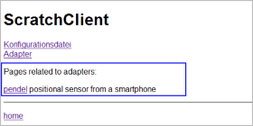
This is the 'injected' web link to the main page.
Adapters get created (instantiated) by the configuration manager when reading the xml-file. When no errors occur, the configManager keeps the instance in a list of adapters for later reference.
Then parameters are set.
Adapters are started one after the other by setActive (True). There is no particular order within the adapters to get this event.
|
If your application needs adapter 'A' to be startet after 'B', then most possibly you need a special implementation 'AB' which combines the two. |
When set to active, adapters should start regular work. This means to setup the GPIO, starting threads and whatever else might be needed. Setting the GPIO can be done by using the base adapter class' methods.
Adapters stop operation by setActive(False). Then threads should be stopped in a timely manner (less than 0.1 sec), and GPIO should be reset to default state. The adapters base class provides mechanisms to setup GPIO. These can be overwritten to achieve other behaviour.
There is no live after setActive(False). The adapters will be destroyed later and the code stops to work.
CPU load
Adapters should not poll and send values too often. Faster than some 20 to 50 updates per second are a challenge for the system, as the socket connection
and also scratch on the receiving end needs cpu-cycles to perform work.
Currently, each sensor-update is send separately.
For the GPIO-Types, different libraries can be used: RPi.GPIO (default) or RPIO. RPIO has the ability to PWM drive the GPIO with DMA, producing stable pulses.
GPIO Pins are named in BCM-Notation (e.g. GPIOnn), Pin headers (e.g. P1-13V2 for Version2) or other (for a specific adapter, IKG.IO.3 is used). The naming configuration is in /scratchClient/config/portMapping.xml
Input type adapters read Buttons, switches and other type of binary signals.
-
adapter.gpio.GpioInput (sends value 0 for low, 1 for high input levels)
-
adapter.gpio.GpioValueInput (sends configurable values for low, high input levels)
On startup or whenever a value change is detected, the adapter sends configurable values. The level assignments can be changed.
-
adapter.gpio.GpioButtonInput (deprecated, use GpioEventInput; sends events on button pressed, button released)
-
adapter.gpio.GpioEventInput (sends events on button pressed, button released)
A nice application is the marshmallow button: two wires through a marshmallow form a contact: when squeezed, the button is pressed. See config/marshmallow.xml .
-
adapter.gpio.GpioOutputPWMServo, pwm is 1ms (0 input value) to 2ms(100 input value), period length 20ms. The PWM adapter uses rpi.gpio library with soft-pwm. This causes jitter for the signals.
The output of this adapter can be inverted by configuration. This is needed if a simple (inverting) transistor level shifter is used.
An adapter designed to monitor the connection state with scratch is adapter.gpio.GpioStateOutput. When the scratchClient is started, the output is set to 'high'. When connection to scratch is established, the output blinks at 0.6 sec cycle time. Please note the naming of the port: these names are configurable as described in Section 10.2, “GPIO Names” .
    <adapter class='adapter.gpio.GpioStateOutput'  name='state'>
        <description>State display on IKG.IO.9</description>

        <gpio port='IKG.IO.9' alias='state'>
            <default dir='OUT'  default='low' />
            <active  dir='OUT'  default='low' />
        </gpio>
    </adapter>
SHT015 humidity Sensor is using a 'wire' protocol, driven by GPIO. The protocol is not time critical. Adapter is adapter.wire_gpio.Wire_SHTx
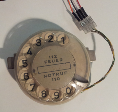
A dialplate as seen here has two switches.
-
Contact 'nsi' is delivering pulses.
-
Contact 'nsa' is closed when the plate is turned.
The adapter adapter.encoder.GPIODialPlateEncoder is handling the plate. It needs two GPIO pins. Polling interval is changing for this adapter. When not used (contact 'nsa'), the polling interval is 0.2 sec. When active the polling interval is 5ms.
The adapter uses polling and is not very accurate. The advantage is that only one GPIO pin is used.
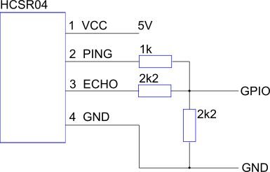
In the python environment used there are threading, garbage collection and of course influences from the operating system. From time to time there are situations where the polling detects timeouts. These situations are reported in the log file like
adapter.gpio - WARNING - HCSR04: error code 2
SPI is a communication protocol for various devices. A concept of 'device handlers' is used to generalize the usage. When in a device multiple similiar data points are used, this is called 'channels'; used in e.g. ADC-devices.
The adapter adapter.spiAdapter.MAX31855_Adapter provides three output values: temp_intern, float value, scaled to °C temp_wire, float value, scaled to °C the error bits of the device are converted to a string value. temp_error, string value,
-
'' empty string, no error
-
'SCV: short to Vcc'
-
'SCG: short to GND'
-
'OC: open circuit'
start scratchClient
cd ~/scratchClient
sudo python src/scratchClient.py -config config/config_max31855.xml
The MCP23S17 is a SPI connected port expander with 16 GPIO pins. The adapter adapter.mcp23s17.MCP23S17_Adapter controls this device.
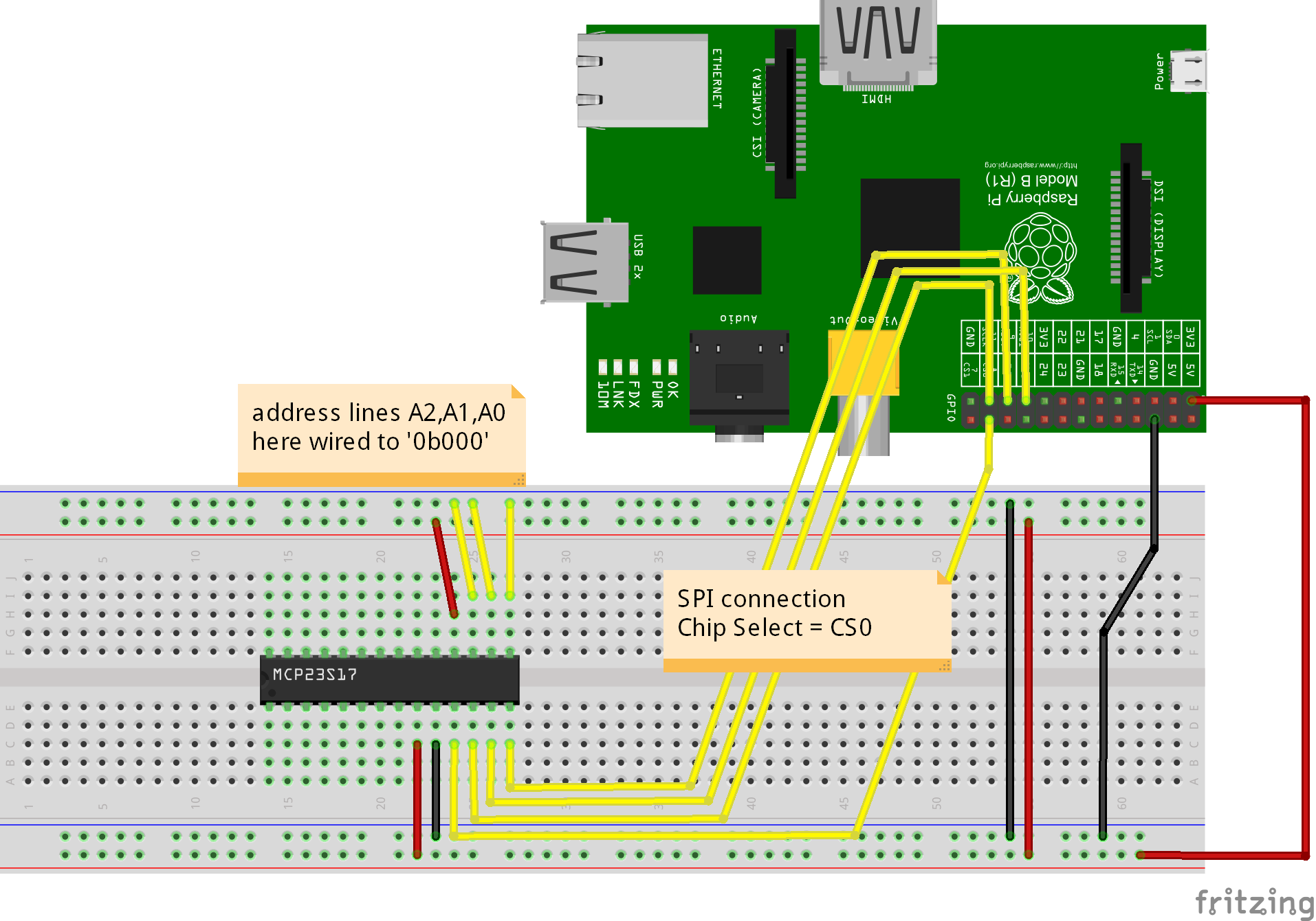
The MCP23S17 is used on the PiFace board. The sample configuration config/config_mcp23s17.xml can be used to drive this board. When using piFace, then do NOT use GPIO25 (this is INTB in MCP23S17)
In scratch, create variables 'out_0', 'out_1' .. 'out_7' to drive the outputs. Values are '0', '1', 'true', 'false'. For the relais, the variables 'relais_0', 'relais_1' can be used. The variable 'all' sets all outputs in parallel.
scratchClient sends sensor values 'inp_0', 'inp_1', .. 'inp_7'; the values are '0' and '1'.
In the configuration file, the scratch names can be changed to be more useful. If for example a 'forwardMotor' is attached to relais_0, just rename 'relais_0' to 'forwardMotor'.
The device 23s17 allows to have up to 8 devices 'in parallel' on one SPI chip select. These devices have hardwired distinct slave adresses. In the configuration, this slave address must be given by the parameter '23s17.addr'.
        <parameter name='spi.bus' value='0' />
        <parameter name='spi.device' value='0' />

        <!-- slave address must match the hard wired slave address
             on the device [0..7] -->

        <parameter name='23s17.addr' value='0' />
The IO direction for the port pins is defined by <io/>-tags.
        <io id='GPA0' dir='out' />
        <io id='GPA1' dir='out' />
        <io id='GPA2' dir='out' />
        <io id='GPA3' dir='out' />

        <io id='GPA4' dir='out' />
        <io id='GPA5' dir='out' />
        <io id='GPA6' dir='out' />
        <io id='GPA7' dir='out' />

        <io id='GPB0' dir='in' pullup='weak' />
        <io id='GPB1' dir='in' pullup='weak' />
        <io id='GPB2' dir='in' pullup='weak' />
        <io id='GPB3' dir='in' pullup='weak' />

        <io id='GPB4' dir='in' pullup='weak' />
        <io id='GPB5' dir='in' pullup='weak' />
        <io id='GPB6' dir='in' pullup='weak' />
        <io id='GPB7' dir='in' pullup='weak' />
It is generally a good idea to define all of the port pins. Technically it is needed to define those which are used in the application. The id-values are predefined and must be used as seen here.
For ports defined as dir='out' outputs, the corresponding adapter input methods can be used:
        <input_value name='inputGPA4'>
            <!-- variable name is the name of the scratch variable
                 which is send out to the adapter. -->
            <variable name='input_4'/>
        </input_value>
For ports defined as dir='in' inputs, the corresponding adapter output methods can be used:
        <output_value name='outputGPB2'>
            <sensor name='output_2'/>
        </output_value>
The variables send out from scratch are '0', '1' to set the output pin of the 23s17 to low, high.
The sensor values received from scratch are '0', '1' for the input pin of the 23s17 receiving low, high.
-
Adapter adapter.adc.ADC_MCP3202_10_Input 10 bit resolution.
-
Adapter adapter.adc.ADC_MCP3202_12_Input 12 bit resolution, providing an optional low pass filter
-
Adapter adapter.adc.ADC_MCP3008_10_Input 10 bit resolution.
8 channel single ended input operation of this device.
SPI can be used to emulate a shift register, as needed by a LED Strip with WS2801-Chip. The adapter is adapter.spiadapter.WS2801_Adapter.
In the distribution, there is a sample scratch program for the WS2801-stripe.
Start scratch with command
scratch ~/scratchClient/scratch/ws2801/ws2801.sb
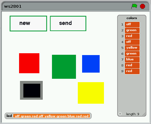
The program provides some colored fields which can be clicked and add their color name to a list. When the data shall be send to the stripe, press 'send'. The list is converted to a variable 'led' then.
The scratchClient adapter converts color names to RGB-values and sends them out to the SPI-hardware.
start scratchClient
cd ~/scratchClient
sudo python src/scratchClient.py -config scratch/ws2801/config_spi_ws2801.xml
For the hardware connection, see your vendors documentation on the stripe.
The Adapter adapter.i2cAdapter.ADC_ADS1015_Input reads values from an ADS1015. The company adafruit sells a breakout board with this chip.
See sample configuration scratchClient/config/config_adc_ads1015.xml.
The Adapter adapter.i2cAdapter.Luminosity_BH1750_Input reads values from a BH1750. Values are luminosity in lux (lx).
See sample configuration scratchClient/config/config_luminosity_bh1750.xml.
The Adapter adapter.i2cAdapter.Pressure_BMP085_Input reads values from a BMP085. Values are pressure and temperature.
See sample configuration scratchClient/config/config_pressure_bmp085.xml.
The Adapter adapter.i2cAdapter.PWM_PCA9685 controls this device.
See sample configuration scratchClient/config/config_PCA9685.xml
In scratch, create variables 'channel_0', 'channel_1', .. 'channel_11'. The values are 0..100. Value 0 is no signal; 100 is full cycle filled.
In scratch, create variables 'servo_0', 'servo_1', .. 'servo_11'. The values are 0..100. Value 0 is 1ms; 100 is 2ms in a 20ms period.
The PCA9865 has 12 bit resolution, which is not challenged with values from scratch in range 0..100. This value is choosen for consistency with other adapters.
The Adapter adapter.i2cAdapter.PWM_SN3218 controls the SN3218-chip. This chip is used on piGlow board.
The usual i2cdetect-command does not report this chip. Use the -q-switch for this device.
root@raspberrypi:/home/pi# i2cdetect -y -q 1
     0  1  2  3  4  5  6  7  8  9  a  b  c  d  e  f
00:          -- -- -- -- -- -- -- -- -- -- -- -- --
10: -- -- -- -- -- -- -- -- -- -- -- -- -- -- -- --
20: -- -- -- -- -- -- -- -- -- -- -- -- -- -- -- --
30: -- -- -- -- -- -- -- -- -- -- -- -- -- -- -- --
40: -- -- -- -- -- -- -- -- -- -- -- -- -- -- -- --
50: -- -- -- -- 54 -- -- -- -- -- -- -- -- -- -- --
60: -- -- -- -- -- -- -- -- -- -- -- -- -- -- -- --
70: -- -- -- -- -- -- -- --
root@raspberrypi:/home/pi#
The sample configuration uses some 'common variables. 'all' is used for all LED in sync. The 'branch_0', 'branch_1', 'branch_2' are for the three branches for the piGlow board. The individual LED are addressed with hex numbers, like 'channel_0A' or 'channel_11'. These names are case sensitive.
cd ~/scratchClient
sudo python src/scratchClient.py -c config/config_SN3218.xml
See scratchClient/scratch/SN3218/piglow.sb for a sample scratch program.
Temperature sensor DS1820 needs one gpio pin for the connection. The timing is quite strict, but a kernel driver is available.
Adapter
adapter.w1_gpio.W1_DS1820
uses 'w1-gpio' kernel driver.
Connect ds1820 signal line to GPIO4, pullup needed 4k7 Ohm to 3.3V.
The adapter configuration sample is
config/config_temperature_ds1820.xml
. In this file, you need to configure the address of your ds1820.
-
Connect DS1820 to raspberry pi, dataline is (usually) GPIO4. Add a resistor 4k7 from data to 3.3V.
-
Start kernel driver: For PI2, add a line to /boot/config.txt
dtoverlay=w1-gpio,gpiopin=4
Needs a reboot to take effect.
-
The driver creates a directory in
/sys/bus/w1/devices, which contains subfolders for each DS1820 connected. The name of the folder is composed of a family code and the unique device id.
DS1820 und DS18S20 have familycode 10, DS18B20 use 28 and DS1822 use 22.
check the directory name and configure inconfig/config_temperature_ds1820.xml. Example:<parameter name='w1.device' value='10-0008023b57b9'
The sample configurations contain a config file for this device. Start scratchClient with
cd ~/scratchClient
python src/scratchClient.py -c config/config_temperature_ds1820.xml
For this special purpose, no root permission is needed. The file written by the kernel driver is public for reading.
Scratch installations can cooperate between different computers. This requires some planning for the network infrastructure and of course at least two computer to demonstrate the basics.
scratchClient offers adapters for this purpose
-
scratchCommunicationServer with CommunicationAdapter. This is a simple solution for a 'data distribution', but allows to limit communication channels to specific computers and so keeps control for the admin.
-
MQTT can be used with MQTT_Adapter. This is a standard protocol for Internet of Things IoT and widely used in industry.
Message Queue Telemetry Transport, MQTT is widely used in IoT applications. The protocol allows to publish values or subscribe to values based on 'topic' strings, e.g. 'scratch/data/sensorA'.
For scratchClient, there is an adapter which provides simple access to this protocol. Although advanced features as e.g. encryption are not used, it allows simple experiments with this toolset.
The adapter provides the client side. The server needs to be installed on one machine, clients need network connection to this machine.
Installation for server. The server can be installed on any machine having a fixed ip address.
sudo apt-get update
sudo apt-get install mosquitto mosquitto-clients python-mosquitto
To validate server installation, run in a terminal
ps -ef | grep mosquitto
The response should be something like
mosquit+ 30805 1 0 12:09 ? 00:00:06 /usr/sbin/mosquitto -c /etc/mosquitto/mosquitto.conf
Installation for client side.
sudo pip install paho-mqtt
Please note that client configuration xml files need to be edited with the correct ip address of server.
Limitations: to make experiments with this setup, best case two computers are needed. Scratch may only run once on each machine, so the smallest usable setup are two machines. When e.g. python mqtt clients are used, there is no limitation on the number of additional clients on one machine.
Configuration of the data transmitted are done in config.xml files. A sample is provided in
config/config_mqtt.xml
. The config files for the adapter.iotAdapter.MQTT_Adapter differ from others in the way the scratch variables are defined.
    <adapter class='adapter.iotAdapter.MQTT_Adapter'  name='mqtt'>
        <description>interface to a mqtt-server</description>

        <!--
           this adapter does implicit input_value and output_value-configuration based on the
              content of mqtt-Tag.
              mqtt/publish/@variable definitions are used as scratch variable names.
              mqtt/subscribe/@variable definitions are used as scratch sensor names.
        -->

        <extension>
        <mqtt>
            <publish topic="scratch/sample/a_value" variable="a_value" />
            <publish topic="scratch/sample/b_value" variable="b_value" />
            <publish topic="scratch/sample/c_value" variable="c_value" />

            <subscribe topic="scratch/sample/d_value" variable="d_value" />
        </mqtt>
        </extension>

        <parameter name="mqtt.server" value="192.168.2.160"  />
        <parameter name="mqtt.port" value="1883"  />
    </adapter>
The input_value- and output_value tags are omitted and the variable definitions are taken from the variable names in the mqtt-section.
The related adapter web page displays this adapter as follows:
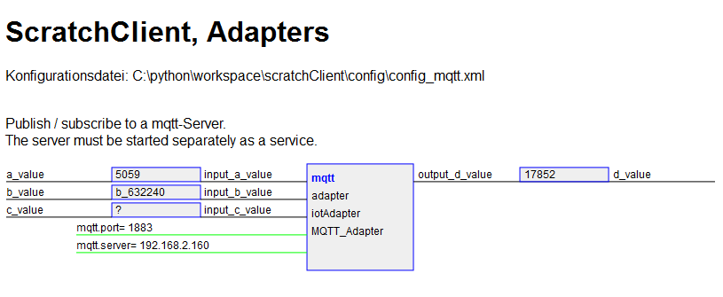
The adapter can be combined with other adapters to read values, write actors or alike.
A typical usage scenario could be that one computer collects some sensor data, e.g. temperature values and provides those with a topic
scratch/sensor/temp
.
Other groups could subscribe to this value and do different things:
-
Display the value for information purpose. Or print a chart based on the values.
-
Switch a heater based on the values. Most possibly a simulated heater when in a school environment.
-
When temperature trend is falling, send a twitter message to the user to buy winter clothes.
Configuration remarks.
Data published by a specific topic are 'send' to all. Anybody can subscribe to the topics to 'receive' these.
Using mqtt in a school lession needs some preparation for topic definition. Which could be an opportunity to talk about hierarchical organization of topic names.
Data published by a specific topic should be received by someone. These subscribe to the topic.
The data send are not events. Scratch does not send out same data multiple times and mqtt just provides values. And the protocol does not care too much about lost communications.
In the distribution, there is a sample for two devices. First device is assumed to be a raspberry pi with a button connected from GPIO17 to GND. Second device is a general purpose computer (or another raspberry pi).
On device_0, when the button is pressed or released, then scratch places an appropriate value into variable 'button' which is published to mqtt, topic 'scratch/sample/button'.
On device_1, the value of topic 'scratch/sample/button' is received and displayed on stage.
Ensure a mqtt server is running and the config files for the sample have the correct ip-address included.
Start scratchClient with
cd ~/scratchClient
python src/scratchClient.py -c scratch/mqtt/dev_0/device_0.xml
scratch scratchClient/scratch/mqtt/dev_0/device_0.sb
The adapter class adapter.remote.CommunicationAdapter provides scratch to scratch communication. There is a server process needed on the network [host, port=42002].
python src/scratchCommunicationServer.py
It is recommended to install scratchCommunicationServer on a machine with a fixed ip address. It can run in parallel to scratchClient on a machine.
The adapters are assigned to groups, so within one network the communication server keeps different groups separate from each other. Sample configuration is /scratchClient/config/config_remote_0.xml or config_remote_1.xml
Groups are useful when in a classroom environment where pairs of two exercise a communication sample, but only one scratchCommunicationServer is running. Then each group gets its own name, and interferences are avoided.
Broadcast signals defined as inputs to the adapter are propagated to all other registered adapters (except the one it came from). Outputs of the adapter are propagated towards local scratch.
A simple szenario is used for the explanation: In a school class, three computers with scratch should perform a chain reaction. 'computer_0' lights a LED and sends 'command_A' to 'computer_1'. When 'computer_1' receives this event, it lights a LED and sends 'command_B' to 'computer_2', which lights a LED.
With an UML sequence diagram, the process gets clear.
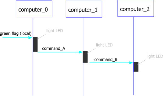
Good planning is needed for a successful setup.
For 'computer_0', there is only one outgoing event.
        <remote type='forward'>
            <broadcast name='command_A'/>
        </remote>
For 'computer_1', there is one incoming event and one outgoing event.
        <remote type='forward'>
            <broadcast name='command_B'/>
        </remote>
        <remote type='receive'>
            <broadcast name='command_A'/>
        </remote>
Finally for 'computer_2', there is one incoming event.
        <remote type='receive'>
            <broadcast name='command_B'/>
        </remote>
For each computer, prepare the appropriate config file and start scratchClient with it.
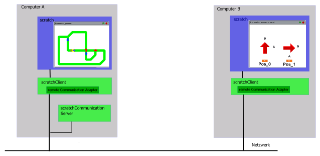
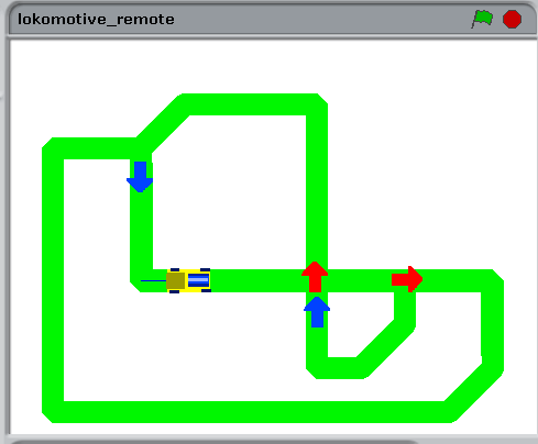
There is a sample implementation of a remote controllable railway track available. To operate this, you need two computers A and B on a network. It is not possible to have this running on one system only, as two scratch instances are needed and the server ports 42001 can't be adjusted. A screencast of this sample is available on youtube
Adjust hostaddress in scratch/remote/config_lokomotive_remote.xml and scratch/remote/config_lokomotive_remote_control.xml, it should contain IP-address or hostname of Computer A.
<parameter name="server" value="192.168.2.102" />
Distribute this file to Computer A and Computer B.
scratch ~/scratchClient/scratch/remote/lokomotive_remote.sb
start scratchClient, in a terminal window.
cd ~/scratchClient
sudo python src/scratchClient.py -c scratch/remote/config_lokomotive.xml
start server process in a terminal window:
cd ~/scratchClient
python src/scratchCommunicationServer.py
scratch ~/scratchClient/scratch/remote/lokomotive_remote_control.sb
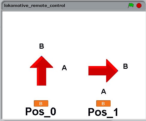
Clicking on the arrows should set the corresponding track directions. But scratchClient needs to be started first. start scratchClient in a terminal window:
cd ~/scratchClient
sudo python src/scratchClient.py -config scratch/remote/config_lokomotive_control.xml
Commands from control panel on computer B scratch instance are transferred to computer A.
Sonic Pi is a sound producing software and programming environment with an excellent sound quality.
The software provides an Open Sound Control OSC-API through an UDP socket. This feature is not documented, so it might be removed silently. In the Release 2.11.1 this feature is available.
This API allows to play sounds like
play 50
or more complex things like
use_synth :chiplead ; play 80,release: 0.08 ; sleep 0.1 ; play 83, release: 0.08
In sonic pi, there is a protocol log which displays commands received and indicates possible errors in syntax.
There are additional installs needed for this adapter.
sudo pip3 install python-osc
The main purpose of this adapter is to have better sound quality from scratch on pi. It is not intended to replace the programming inside sonic pi by scratch, especially as timing can't be as precise from scratch.
When the connection to scratch is enabled or disabled, a small tune is played.
There is a sample config file in config/config_sonicpi.xml.
Usage: start sonic pi on same computer as scratchClient.
The adapter can be combined with other adapters to read values, write actors or alike.
The adapter runs on raspberry pi and windows; it needs python3 for scratchClient.
Sending broadcast events from adapter to scratch when remote communications is established. Use this to start a script automatically.
adapter.broadcast.ScratchStartclickedAdapter
    <adapter class='adapter.broadcast.ScratchStartclickedAdapter'  name='startClick'>

        <output name='command'>
            <broadcast name='scratch-startclicked'/>
        </output>
        <description>Send startclicked</description>
    </adapter>
sends scratch-startclicked when remote communication is established. This is a 'green flag' event for scratch 1.4.
Adapters are not limited to GPIO or SPI based devices, but can control applications on the computer as well. Ad hoc speech synthesis is available with 'festival' or 'pico2wave' text to speech applications, There are audio outputs available in scratch, but only prerecorded snippets. Text to speech allows arbitrary text to be produced. You need to have the tools installed.
Sample configuration is config/config_texttospeech_festival.xml
Sample configuration is config/config_texttospeech_pico2wave.xml
Speech output is quite slow. The adapter queues the incoming data up to a length given by the parameter 'queue.max'. When queue size is exceeded, new entries are discarded and a warning log message is issued.
Comment
Keep in mind that scratch sends values only on changes. Repeating the same text multiple times works only if the text is (silently) modified, e.g. by appending blanks and removing blanks in turn. Festival is well suited for english language. German text will sound a little bit strange. pico2wave has better quality output.
Scratch 1.4 has no system time available. This adapter provides current system time to scratch.
adapter.broadcast.TimeAdapter
See configuration file config/config_time.xml for a sample.
Control applications on the computer with this adapter. It will execute a os-command configured.
Sample configuration is config/config_linux.xml
<adapter class='adapter.linux.Linux_Adapter'  name='sample'>
        <description>linux os command exectution</description>

        <input name='trigger'>
            <!-- scratch event name -->
            <broadcast name='execute'/>
        </input>

        <parameter name="os.command" value="ls -l"  />
        <parameter name="queue.max" value="5"  />
    </adapter>
Start sample configuration
cd ~/scratchClient
python src/scratchClient.py -c config/config_linux.xml
Sample scratch code

Programs executed should not run long time.
The adapter queues the incoming data up to a length given by the parameter 'queue.max'. When queue size is exceeded, new entries are discarded and a warning log message is issued.
The commands executed are configured in configuration file. These commands are execute in the context of the user who started scratchClient. Avoid starting scratchClient as root when in doubt.
Play wav-files using linux aplay command. This adapter allows some more flexibility than the scratch build in audio replay, as the ALSA-device can be defined. On USB-adapters, higher quality can be achieved.
The linux command used is 'aplay -D device dir/file'.
Place the files to play in file system directory. Or use the already available files in e.g. /opt/sonic-pi/etc/samples. These files are NOT included in the scratch code. So when you move your scratch application to another computer, you need to move your files too.
The code snipped shows how to play one sound repeatedly. As scratch only transmits variables when the value changes, the file name is set to 'blank' in between.
Record wav-files using linux arecord command. This adapter allows some more flexibility than the scratch build in recording,and is run time controllable by scripts
The linux command used is 'arecord -D device dir/file'.
Set file name first.
Start recording with an event, and stop with an event. There is a timeout provided in case scratch misses to send the stop event. This timeout feature limits space consumption in file system.
These files are NOT included in the scratch code. So when you move your scratch application to another computer, you need to move your files too.
Protect privacy: do not record personal communication without permission.
There are speech recognition systems available which run on raspberry pi. Pocketsphinx is an example.
Pocketsphinx needs a quite complicated installation procedure. It is described in installation instruction .
Running pocketsphinx in countinuous mode needs quite a lot of CPU power. So I decided to run it in batch mode. This is convenient for short sequences of speech. Use the arecord-adapter to record sound snippets, and process these by the recognition adapter.
For sending text from scratchClient to scratch a protocol is implemented. ScratchClient sets the 'text'-variable, and then sends an event 'textAvailable' (or whatever is configured in the adapter xml). When data are processed in scratch, then scratch sends an acknowledge 'textAcknowledge' to scratch client.
See a scratch sample code in
scratch/linux/speechRecognition.sb
The data received from scratchClient are added to a list. Another script takes these data from the list and displays then with a 'think'-action. Perhaps there are more useful things which could be controlled.
Adjust the command line given in the adapter config file according to your needs and check this first in a terminal window.
<parameter name ='command.line'
           value='pocketsphinx_continuous -hmm /usr/local/share/pocketsphinx/model/en-us/en-us  \
                                          -lm 0609.lm -dict 0609.dic -samprate 16000/8000/48000 \
                                          -logfn /dev/null                                      \
                                          -infile ${sound.dir}/${sound.file}' />
Please note that this command line is from a developement system. The dictionary '0609' was set up for some numbers and commands. This needs adjustment for each environment.
Start this sample with scratchClient
python src/scratchClient.py -c config/config_linux_a_ASR.xml
pocketsphinx prints recognized text line by line; fast spoken words are in one line. Silence breaks cause new lines to be produced.
An UML sequence diagram best explains the sequence of commands and the protocol.
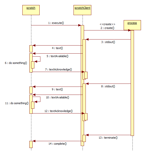
(1,2) The processing is started by an 'execute' event. The linux process is created.
(3..7) A line of text from the process is read into scratchclient and written to a sensor variable 'text'. Then a textAvailable Event is issued and scratch should process the data. When processing is complete, a textAcknowledge event to scratchClient is sent.
(8..12) Just another example of a text sent.
(13,14) If the process terminates, a 'complete'-Event is sent towards scratch.
This adapter is not limited to speech recognition; it can be used with any process which outputs lines of text to stdin.
Linux lirc allows to receive IR control signals. The adapter allows to receive key events and to forwart these to scratch. The adapter does not send commands.
lirc needs to be installed and configured. The installation described here is not a comprehensive tutorial on lirc, but a short summary on what needs to be done.
There are many IR receiver devices. The test device used was a VISHAY TSOP34838; be sure the device is 3.3V compatible
lirc is using BCM port numbering, for this sample the input pin is connected to GPIO17
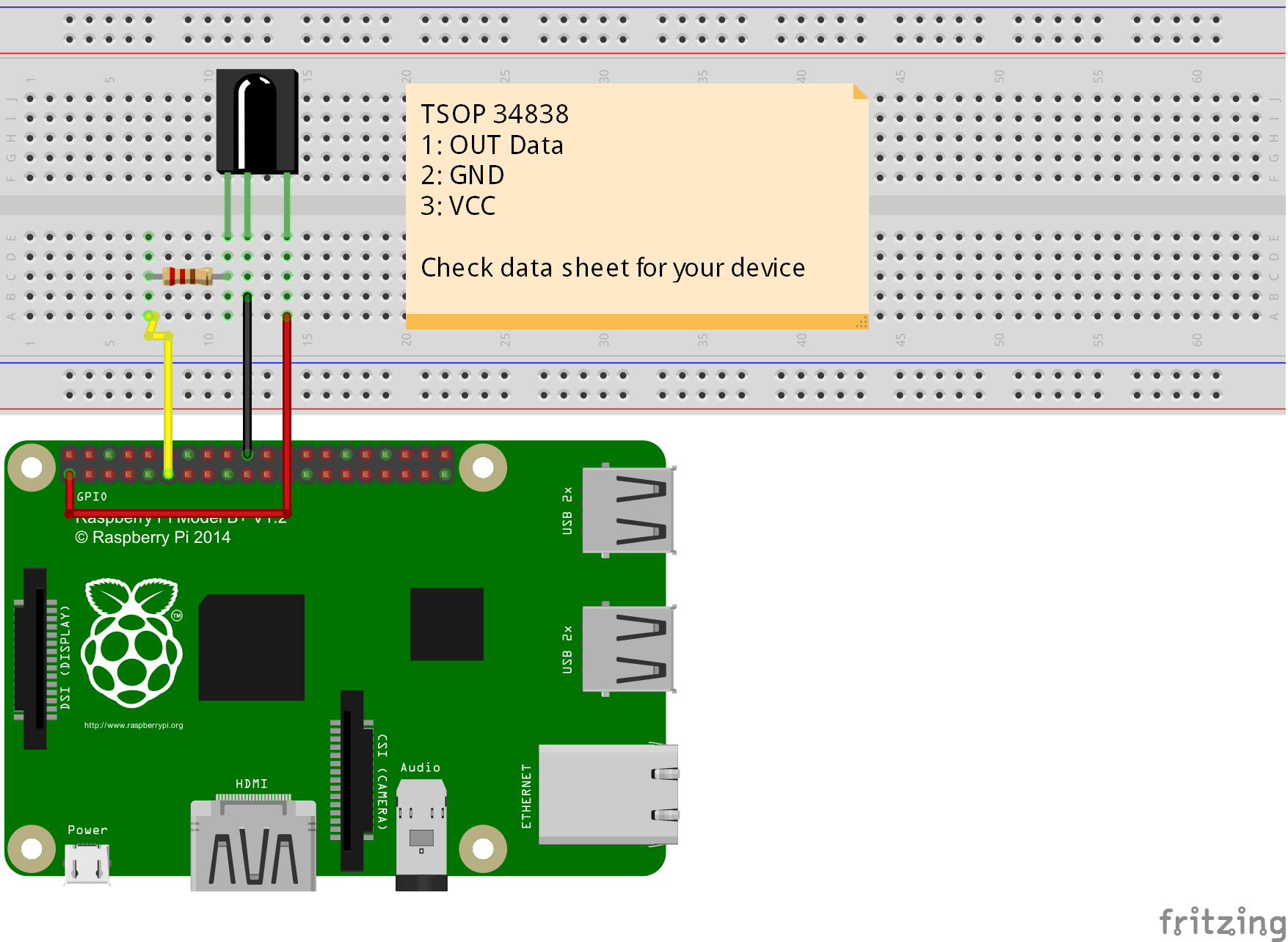
The resistor is 330 Ohm and protects the gpio pin when accidentially switched to output mode.
lirc needs to be installed and configured.
The installation sequence is based on raspberry-pi-fernbedienung-infrarot-steuerung-lirc
The operating system used is Raspbian 2017-04-10; the procedure might change in future releases.
Enable lirc in device tree.
Edit /boot/config.txt
sudo nano /boot/config.txt
From:
    # Uncomment this to enable the lirc-rpi module
    #dtoverlay=lirc-rpi
To:
    # Uncomment this to enable the lirc-rpi module
    dtoverlay=lirc-rpi

    # Uncomment this to override the defaults for the lirc-rpi module
    #dtparam=gpio_out_pin=16
    dtparam=gpio_in_pin=17
    #dtparam=gpio_in_pull=down
Install lirc
sudo apt-get update
sudo apt-get install lirc -y
Edit /etc/lirc/hardware.conf
sudo nano /etc/lirc/hardware.conf
    # /etc/lirc/hardware.conf
    #
    # Arguments which will be used when launching lircd
    LIRCD_ARGS="--uinput"

    #Don't start lircmd even if there seems to be a good config file
    #START_LIRCMD=false

    #Don't start irexec, even if a good config file seems to exist.
    #START_IREXEC=false

    #Try to load appropriate kernel modules
    LOAD_MODULES=true

    # Run "lircd --driver=help" for a list of supported drivers.
    DRIVER="default"
    # usually /dev/lirc0 is the correct setting for systems using udev
    DEVICE="/dev/lirc0"
    MODULES="lirc_rpi"

    # Default configuration files for your hardware if any
    LIRCD_CONF=""
    LIRCMD_CONF=""
Verification
Stop lirc
sudo /etc/init.d/lirc stop
Check receiver with
mode2 -d /dev/lirc0
, press buttons on remote control, you should get something like
   space 958099
    pulse 896
    space 890
    pulse 892
    space 897
    pulse 1795
    space 890
    pulse 902
Stop lirc
sudo /etc/init.d/lirc stop
List available commands for the key events
irrecord --list-namespace | grep 'KEY'
. Use only names out from the listed commands for your remote control.
Register remote control key presses by
irrecord -d /dev/lirc0 ~/lircd-remote.conf
Read the irrecord printouts and confirm with enter twice. Press different remote buttons for each prox a second until you get message
Please enter the name for the next button (press to finish recording)
Use only codes you recorded earlier, e.g. 'KEY_0'
When finished, terminate program and edit new conf file to change name of remote control.
nano ~/lircd-remote.conf
Copy new conf file to /etc/lirc/lircd.conf
sudo cp ~/lircd-remote.conf /etc/lirc/lircd.conf
Start lirc
sudo /etc/init.d/lirc start
check commands using 'irw' this tool displays actions provided by lirc
					pi@raspberrypi:~ $ irw
					0000000000001005 00 KEY_5 /home/pi/lircd-fernbedienung.conf
					0000000000001005 01 KEY_5 /home/pi/lircd-fernbedienung.conf
					0000000000001002 00 KEY_2 /home/pi/lircd-fernbedienung.conf
sudo pip install evdev
					sudo pip3 install evdev
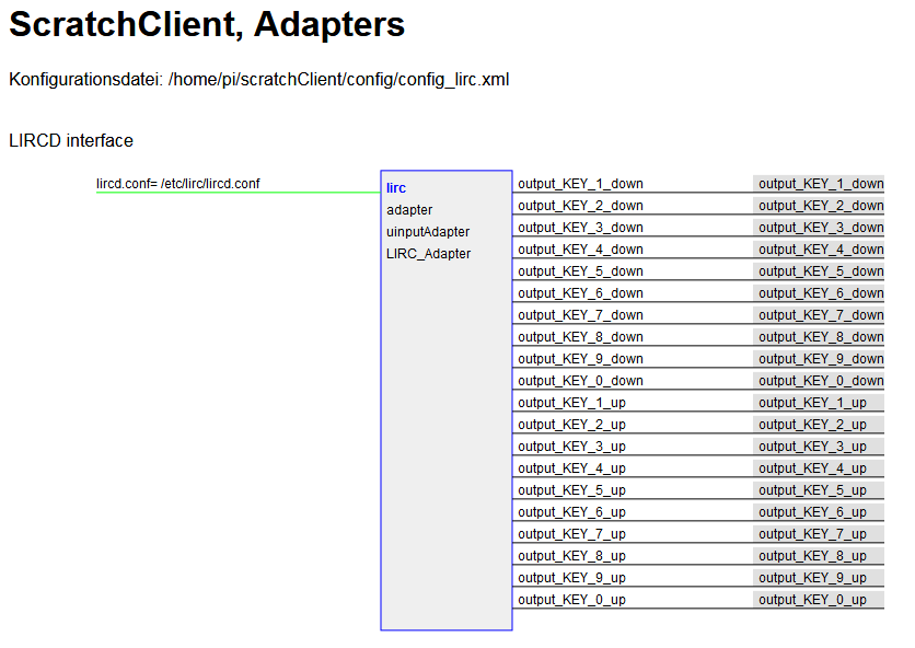
Adapter maps KEY events to signals for scratch. Signal names are build by 'output_' + KEY-name + '_up' or 'output_' + KEY-name + '_down'. Examples are "output_KEY_6_down" or "output_KEY_9_up" .
The key names are read from lircd config file, usually in /etc/lirc/lircd.conf
In the web monitor, the adapter is displayed with the events retrieved from config file.
When looking for inexpensive, breadboard-friendly AD-Converters the popular Atmel atmega328 can be used. This device has an 8-channel AD-Converter. The controller needs a custom firmware, is interfaced by SPI and provides a switchable LED. A description is available on my website heppg.de, “Atmel 328-Prozessor als AD-Wandler”. The SPI communication is choosen, as it is used to flash the chip and wiring is available. Interfacing this device to scratchClient needs SPI communication and the RESET-Line for the processor. The adapter adapter.atmel328_adapter.Atmel328_ADC_Adapter provides functionality for this setup. It is not generic, but a proof of concept for a SPI/GPIO based setup. Sample configuration is in config_adc_atmel328.xml.
The firmware in the atmega328 allows for frequency measurement. See 'steckbrett_328_en.pdf' for reference.
Sample configuration is in config_adc_atmel328.xml
The remote coprocessor is connected by SPI.
There is a firmware for the DHT22, DHT11 device.
The temperature, humidity sensor DHT22 is a quite inexpensive sensor, well suited for microcontroller applications. It uses same protocol as DHT11. It is connected by a single wire, needs 5ms for a read cycle, but a quite challenging protocol where the pulse width gives '0' or '1' bit values.
This is a typical application for a coprocessor for raspberrypi. For an atmel328, it is not a challenge to handle this protocol.
Sample configuration is in config/config_dht22_atmel328.xml
The remote coprocessor is connected by SPI.
For testing purposes, there is the need for looking into details of the communication protocol, and sending values to scratch without the need for attached hardware.
adapter.test.TestAdapter
sends values towards scratch, changing each cycle.
When only this adapter is configured, then scratchClient does run also on windows or other hardware than raspberry pi.
Values send every second.
-
iValue, integer values, incremented
-
sValues, string values with 'umlaut' utf-8 chars
['apfel', 'apfeläöü', 'äöü' ] -
fValues, different decimal places, including 19.0
[18.8, 18.9, 19.000, 19.123, 19.2]
Values send only once at startup
-
test22, integer value 1; use the web interface at localhost:8080 to edit and send values as needed.
Events
-
event 'testEvent'
Start of scratchClient:
cd ~/scratchClient
python src/scratchClient.py -c config/config_test.xml -d
No superuser rights are needed for this setup, as no hardware specific drivers are connected. When running scratch on a different host, use command line
switch
-host [ip]
to connect to a remote scratch instance.
Servoblaster is software to DMA-control servo units with pulses from 1 to 2ms, frequency 50 Hz.
It can also be used to full scale pwm control signals to drive LED or alike, but current implementation of the adapter only supports servo signals.
The software is controlled by writing commands to /dev/servoblaster; example is
echo '5=1200us' > /dev/servoblaster
The adapter adapter.servoblaster.ServoBlaster is controlling 8 channels, see config file config/config_servoblaster.xml for a sample configuration.
Please note that the integration into the GPIO-system of other adapters is not available, so duplicate use of GPIO will not be detected.
Scratch can send values from 0..100, which corresponds with 1ms to 2ms servo signals.
The adapter writes to /dev/servoblaster, there are checks whether this pipe exists. A reconnect logic handles restarts of servoblaster daemon.
#
# start servoblaster daemon separately, it is not started by scratchClient !
#
cd ~/scratchClient
python src/scratchClient.py -c servoblaster
The config file sample is
config/config_servoblaster.xml
.
Precise PWM signals can be achieved by using DMA on raspberry pi. Such sinals are used to control servo or to dim LED.
In the scratchClient distribution, there is a library RPIO2, derived from RPIO package. The PWM part of this lib is ported to work on RPI3 too.
See chapter on installing RPIO2 and there is an adapter to use it.
Sense Hat provides many different sensors and a LED matrix.
This board needs special installation procedure, see pythonhosted.org/sense-hat
LED matrix single pixel, sensors and orientation is supported.
Sample code is in
scratchClient/scratch/senseHat
With cursor keys, move the selector border to a led. With blank key toggle the LED to a lolor or dark.
Scratch sample code:
scratchClient/scratch/senseHat/sense_hat_led.sb
scratchClient config file:
scratchClient/scratch/senseHat/config_senseHat.xml
In order to keep the scratch code simple, this special adapter uses a special pattern for parameter passing to sense-hat function call: variables sent are stored in adapter and used for function events later.
The advantage of this pattern is that code is clear, but this pattern can only be applied when setting the parameter values is not done in multiple places.
To set single pixel values it is needed to set x_pos, y_pos and color first before broadcast setPixel_xy.
To clear single pixel values it is needed to set x_pos, y_pos first before broadcast clearPixel_xy.
Alternative way would be to use 'composite broadcasts', where command and parameters are joined to one event.
PianoHat is a cpacitive button board.
This board needs special installation procedure, see Getting started with Piano HAT
Sample configuration is
scratch/pianoHat/config_pianohat.xml
In a quite popular computer magazine, c’t 2015-03-07 (heise verlag), there is a nice article about how to connect a smartphone’s positional sensors to a remote server by using a web page, some javascript and websockets.
Starting from this, there was the idea to connect this to scratch (what else ?).
The basic roadmap was
-
add a html-page to my scratchClient’s web server, with javascript
var addr = "ws://" + window.location.hostname + ":" + window.location.port + "/pendel"; var websocket = new WebSocket( addr ); function handleOrientation(event) { var x = event.beta%90; var y = event.gamma; x += 90; y += 90; try { websocket.send(JSON.stringify( { x:x, y:y })); } catch(err) { // console.log( err.message ); } } window.addEventListener('deviceorientation', handleOrientation); -
in scratchClient, there is cherrypy used to serve the web pages. WebSocket was a new feature to be added there.
-
an adapter needed to be written adapter.websocket.WebsocketXY_Adapter, receiving the messages and converting them to scratch variable updates.
Installation of scratchClient now needs ‘ws4py’ in addition to cherrypy. See the installation description.
cd ~/scratchClient
sudo python src/scratchClient.py -c config/config_websocket_pendel.xml -guiRemote
The guiRemote-switch is needed to allow remote browsers connecting to scratchClient.
In a smartphone browser, navigate to your pi’s address. Of course you need a (wireless) network connection between smartphone and raspberry. In my network, the RaspberryPi’s address is 192.168.2.90, most possibly different for your PI. Use ‘ifconfig’ to look it up.
http://192.168.2.90:8080
Navigate to “Smartphone as Sensor” browser
You should see rectangle with a red/green dot moving around. This is as proposed by the c’t-article.
In scratch, enable remote sensor connections and provide the following script. gotoX and gotoY are sensor values provided by the scratchClient. The xl and yl-Variables are local variables in scratch.
The x and y-values are getting exchanged and the y-value gets inverted to match the coordinates of the smartphone to scratch stage.

Barcode scanners are USB-connected devices.
These scanners typically can send codes by emulating HID-class devices. This makes usage from programs quite easy, but you loose input when the program goes to background and other programs get the focus.
Connecting these devices can be don eusing pyusb library. This library allows access to usb devices and, very important, can grab devices to be used exclusively by one program.
Here I found a problem. The usual install did not workwith „pip install pyusb“. This resulted in a 'backend not found' exception and „undefined symbol: libusb_strerror“
When I tried to download walac-pyusb-50b1490 from https://github.com/walac/pyusb, this worked, but I had to uninstall the pip-installed code first „sudo pip uninstall pyusb“.
The needed backend packages are already available in raspbian, you can check this with
apt-cache pkgnames | grep libusb
You should find libusb-1.0-0 in the list.
A few preparations are needed with the scanner to enable HID mode. With my scanner I got a handbook with a huge amount of programming codes. You start programming with a 'start programming' code, scan the appropriate setup code and exit programming with an 'end programming' code.
For my sample, I have setup HID mode, and added exit code/suffix CR. This is needed to detect complete sequences. The adapter in scratchClient relies on this.
Another preparation is the configuration of idVendor and idProduct in the adapter's config file. Use the utility enum.py to list the devices available
cd ~/scratchClient
python tools/usb/enum.py
Here the output for my scanner
DEVICE ID 0c2e:0200 on Bus 001 Address 007 =================
bLength : 0x12 (18 bytes)
bDescriptorType : 0x1 Device
bcdUSB : 0x110 USB 1.1
bDeviceClass : 0x0 Specified at interface
bDeviceSubClass : 0x0
bDeviceProtocol : 0x0
bMaxPacketSize0 : 0x8 (8 bytes)
idVendor : 0x0c2e
idProduct : 0x0200
bcdDevice : 0x5881 Device 88.81
iManufacturer : 0x1 Honeywell Scanning and Mobility
iProduct : 0x2 Honeywell Scanning and Mobility Scanner
iSerialNumber : 0x0
bNumConfigurations : 0x1
CONFIGURATION 1: 300 mA==================================
bLength : 0x9 (9 bytes)
bDescriptorType : 0x2 Configuration
wTotalLength : 0x22 (34 bytes)
bNumInterfaces : 0x1
bConfigurationValue : 0x1
iConfiguration : 0x3 HID Keyboard
bmAttributes : 0x80 Bus Powered
bMaxPower : 0x96 (300 mA)
INTERFACE 0: Human Interface Device ====================
bLength : 0x9 (9 bytes)
bDescriptorType : 0x4 Interface
bInterfaceNumber : 0x0
bAlternateSetting : 0x0
bNumEndpoints : 0x1
bInterfaceClass : 0x3 Human Interface Device
bInterfaceSubClass : 0x1
bInterfaceProtocol : 0x1
iInterface : 0x0
ENDPOINT 0x81: Interrupt IN ==========================
bLength : 0x7 (7 bytes)
bDescriptorType : 0x5 Endpoint
bEndpointAddress : 0x81 IN
bmAttributes : 0x3 Interrupt
wMaxPacketSize : 0x8 (8 bytes)
bInterval : 0xa
What you also should check is the iConfiguration to be a HID Keyboard.
For verification open a text editor like leafpad: when scanning a code, this should be entered into the editor as a text string.
Edit config/config_barcode.xml and adjust the vendor/product id there.
In my environment, I use a powered USB hub to connect the scanner.
cd ~/scratchClient
sudo python src/scratchClient.py -c config_barcode
The file config/config_barcode.xml is a starting point for a project. Add other adapters as needed. When scanning barcodes, these are send to scratch. Do not forget to enable remote sensor connections.

Blink is a small, USB based device with two RGB-LED.
Connecting this devices can be done using pyusb library. This library allows access to usb devices and, very important, can grab devices to be used exclusively by one program.
See chapter 'install pyusb' in barcode scanner chapter' for installation .
Receiving and sending SMS text messages is possible with the adapter adapter.serialAdapter.SIM800_Adapter. The hardware ist the adafruit fona SIM800 breakout board. Connection is made from rx, tx to the tx, rx of the RaspberryPi. Follow the instructions from adafruit to setup the module.
For this board, you need
-
a SIM card
-
Lipoly Battery, 500mA or larger
-
micro USB charger for the board in addition to this needed for Raspberry Pi
-
antenna
Basic hardware setup, cited from adafruit webpage.
Vio - THIS IS THE MOST IMPORTANT PIN! This is the pin that you MUST drive with an external voltage from 3V-5V to set the logic level converter. The converter
also buffers the indicator LEDs so NOTHING will appear to work unless this pin is powered! You should set the voltage to whatever voltage your
microcontroller uses for logic. A 5V micro (like Arduino) should have it be 5V, a 3V logic micro should set it to 3V.
For SMS, I did not use the other connectors. For automated startup, the 'Key' would be nice to use.
Rx,Tx are connected to the Raspberry. If you are not sure on wiring, use serial 1kOhm to protect the Pi.
Software installation hints:
The /dev/ttyAMA0 must be removed from the /boot/cmdline.txt and /etc/inittab.
For python, install pyserial
sudo pip install pyserial
Edit the configuration file
~/scratchClient/config/config_sim800.xml
:
-
provide the phone number to send sms to
-
and provide the pin for the sim card.
        <parameter name='sim.pin' value='NNNN' />
        <parameter name='remote.number' value='NNNNNNNNNNNN' />
Start the scratchClient with
cd ~/scratchClient
sudo python src/scratchClient -c config/config_sim800.xml -d
The debug switch is highly recommended, as error output is available only in the log file.
Manually start the modem by pressing the button on the breakout board. This is by purpose not automated, in order to have control on cost by sending sms. In scratch, the variable sim_out is used to transmit the sms send request. Empty (blank) strings will not be transmitted. The sensor value sim_in receives the values from the modem.
|
Please be aware that sending sms causes cost. Sending rate with programs can be quite high, so carefully check the logic. For this reason, no automatic startup of the modem is provided, which allows some control on when the modem is available. |
The adapter is adapter.serialAdapter.RFID_Reader_Adapter, a sample config file is in config/config_ID12LA.xml.
RFID-Readers are available for 125kHz and 13.56MHz. For the 125kHz there are reader modules available from Innovations which contain also the antenna.
Connect the device to 3.3V and set format to ASCII. The data output goes to Rx-Input of Raspberry Pi.
The adapter sends an event when data are received from RFID-reader. This allows to trigger scripts in scratch when the same card or tag is used twice.
The adapter is adapter.serialAdapter.PicoBoard_Adapter, a sample is available in /config/config_picoBoard.xml.
Picoboard, available from sparkfun, is a USB/serial connected device which contains some sensors and a slider.
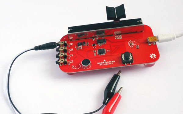
The serial protocol is using polling. Scratch or the adapter in scratchClient sends out a 0x01 to start data aquisition and transfer. The board responds by 9 datapackets.
-
channel 15, softwareversion 0x04
-
channel 0, sensorD
-
channel 1, sensorC
-
channel 2, sensorB
-
channel 3, button, open = 1023, 0 pressed
-
channel 4, sensorA
-
channel 5, light sensor, bright 0, dark 1023
-
channel 6, sound sensor, loud 1023, silent 0
-
channel 7, slider sensor, 0..1023
As polling is used, the tx and rx-LED should flicker frequently.
| Byte | Bit | Content |
|---|---|---|
| byte 0 | 7 | '1' |
| byte 0 | 6..3 | channel |
| byte 0 | 2..0 | high 3 bytes of value |
| byte 1 | 7 | '0' |
| byte 1 | 6..0 | low 7 bytes of value |
This board is supported by scratch, so usually there is no need to use scratchClient.
There are situations where support by scratchClient is useful:
-
When you need more than one board.
-
You want to see the native values delivered by picoBoard.
The sample configuration file config/config_picoBoard.xml uses the scratch names used from ScratchBoard.
If you need more than one picoboard, then
-
duplicate the
<adapter/>section in config/config_picoBoard.xml. -
rename adapter/@name from 'picoboard' to 'picoboard_0', 'picoboard_1' (or to any unique name you like)
-
rename the adapter/output_value/sensor/@name values to unique names to make these separate for each adapter.
e.g.
adapter/output_value/sensor[@name='slider'] [1] /@name to 'slider_0';
adapter/output_value/sensor[@name='slider'] [2] /@name to 'slider_1' -
rename parameter [@name='serial.device'] to match each picoboard, most probably /dev/ttyUSB0, /dev/ttyUSB1
Arduino UNO has an USB connection, which supports serial connection to a host computer. The arduino can be used as a IO expander, connecting digital io lines, pwm, or adc-inputs directly to scratchClient. It also supports servo signals (pwm 50Hz, 1 to 2ms pulses) by the Servo library.
The arduino sketch provided allows to use counters on inputs. The low to high-edge of signals will be counted, there is a 4ms debounce time and max frequency is prox 80Hz.
The adapter and arduino sketch will work with arduino nano, atmel328 processor, 16MHz.
With the USB-connection, the UNO provides 5V-compatible inputs/outputs. This is an advantage in some constellations. But do not connect these outputs back to Raspberry Pi inputs directly.
The functionality presented here is not a bridge to mesh network, propagating events and sensor updates into the arduino. There is a custom arduino sketch needed which only exposes the IO resources, but does not allow for additional logic in arduino.
Configuration of the io-pins (direction, pullup, pwm, servo, counter) and adc-pins (analog, input or output) is controlled by scratchClient through configuration. There is no need to adjust the arduino firmware for config changes.
The scratch names used are configurable in configuration too. This is common functionality of the framework.
The code for the arduino, a sample configuration and a sample scratch project are contained in the scratchClient distribution.
Start arduino software, load arduino/arduinoUno/arduinoUno.ino and program it into the UNO.
The LED13 on the arduino should blink at 5Hz, quite fast. This indicates that the firmware did not yet receive configuration.
This setup is a sample for what is possible with this setup. The configuration file allows for almost all the flexibility the atmel controller allows.
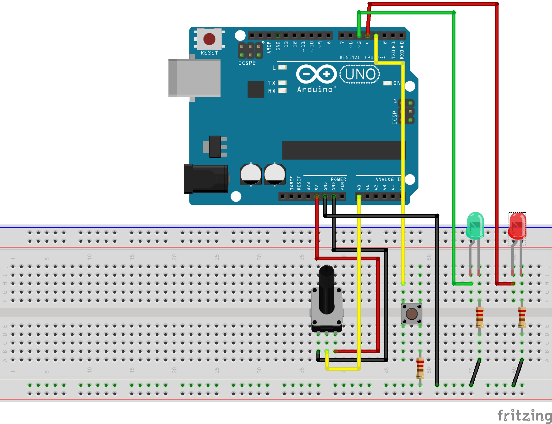
The hardware uses a potentiometer (2k to 10k are ok) on AD0. On D3, there is a button connected. The other side is having a 1k-Resistor to GND (just in case the output is configured as an output, this prevents damage to the IO).
Two LED are for output. The green LED is on a PWM-Output D5, so it can be dimmed.
This setup is a sample. The functionality of all the inputs and outputs are defined by configuration in scratchClient.
On raspberry, lookup /dev /tty* connections and configure the UNO serial device in config/config_arduino_uno.xml-File.
For windows, you see the COMn-Device used in deviceManager.
cd ~/scratchClient
python src/scratchClient -c config/config_arduino_uno.xml
After a short while, the LED13 should start blinking at 1Hz, quite slow. This indicates that configuration was downloaded and operation is ready to be used.
There is a sample program in scratch/arduinoUno/arduino.sb
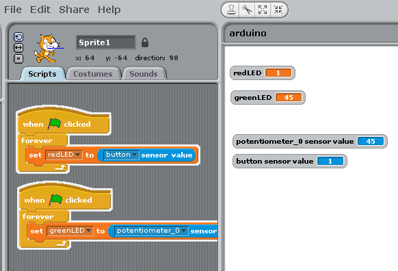
The program takes the button input and controls the red LED with it.
The value from the potentiometer is used to set the pwm-rate and dim the green LED.
The setup of a xml config file for this adapter is not easy. There is a configuration tool available for this adapter.
The tool is written in java.
Start with
cd ~/scratchClient
cd tools
java -jar scratchClientConfig.jar
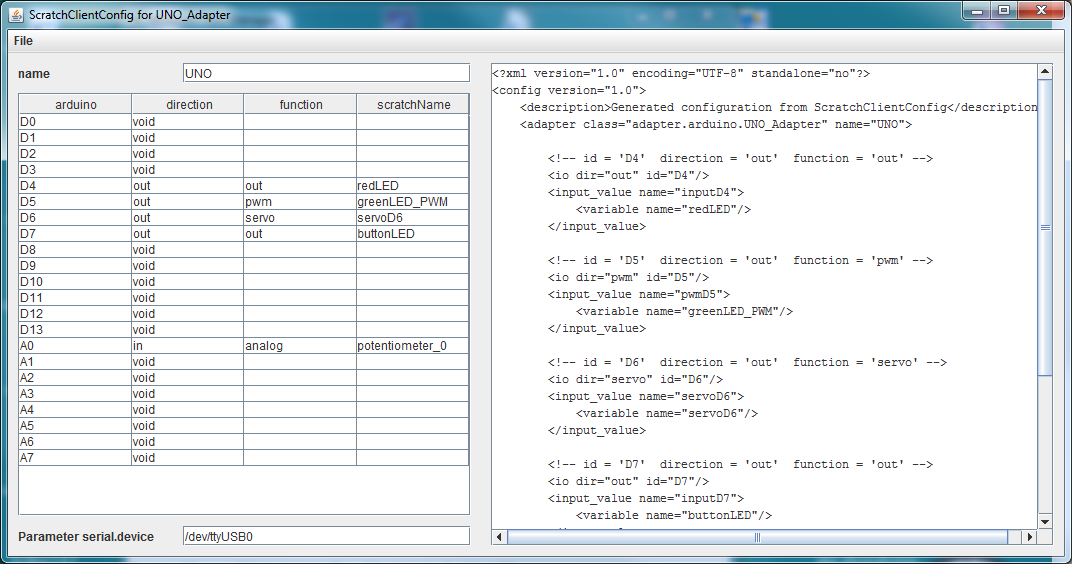
Limitations
The tool only allows to handle config files with one adapter of type 'adapter.arduino.UNO_Adapter'.
The adc-channel needs to be limited to 10Hz updates. There is averaging for three samples per value transmitted. Without a limit to 10Hz, a noisy input could flood the communication line with data and cause excessive cpu usage on a raspberry pi.
The adc-channels on Port A allow for analog inputs, digital inputs or for digital output.
PWM pulses are created with analog_write on the digital pins. According to the arduino reference, analogWrite() works on pins 3, 5, 6, 9, 10, and 11. Input values for pwm are 0..255.
Servo pulses are created with Servo-library. See limitations of this library in Arduino Servo . Input values for servo are 0..180.
Digital inputs can be used with counter functionality. Low to high edges are counted, there is a 4ms debounce time on the edges. Max frequency is prox 80Hz. Values are 32 bit, the values will overflow (which rarely will happen).
Configuration is not persisted in the arduino.
Configuration is requested to be sent from RaspberryPi or windows to arduino on reset of arduino. If scratchClient configuration is changing, then a reset on arduino is needed to make this active. As in most cases a hardware change is made with arduino disconnected from power (either USB cable or power plug), this is only a small limitation.
One of the advantages is that e.g. windows scratch 1.4 with scratchClient on windows allows for IO connections.
The communication between arduino and host computer on the serial file is in a human readable protocol.
Configure arduino IDE serial console to 115200Bd, 8N1, newline (LF, 0x0a) to use the low level interface for the arduino.
On reset, the arduino starts to request for configuration
arduino sending@115200 Bd
arduinoUno, version 2016-11-13
config?
config?
config?
Available commands are reported by sending 'help' to the arduino.
arduino requests configuration with 'config?' on reset

Configuration commands
 cdebug:<data>      debug settings, data are hex (0,1,2,3)
 cr:                dummy request, just get a newline and clean buffer
 cversion?          request version string
 cerr?              request error count for parser
 cident?            request idcode
 cident:<char16>    write idcode
 cident:            reset idcode

 char16 = [A-Za-z][A-Za-z0-9-_.]{1,15}

 cdin:<data>        digital inputs, data are hex
 cdinp:<data>       digital inputs, pullup enabled
 cdcnt:<data>       digital inputs for a counter
 cdcntp:<data>      digital inputs for a counter, pullup enabled
 cdout:<data>       digital outputs
 cdpwm:<data>       digital pwm
 cdservo:<data>     digital servo
 caain:<data>       analog line, analog input [a0..a5]
 cadin:<data>       analog line, digital input [a0..a5]
 cadinp:<data>      analog line, digital input, pullup [a0..a5]
 cadout:<data>      analog line, digital output

 data give bit patterns for IO pins, hex coded

Commands to set values in arduino
 o<port>,<value>    write output
 oa<port>,<value>   write output analog line
 p<port>,<value>    write pwm
 s<port>,<value>    write servo

Values reported from arduino
 v:<version>        report version
 ident:<char16>     report ident from EEPROM
 e:<errors>         report number of errors (decimal)
 a<port>,<value>    report analog input
 i<port>,<value>    report digital input
 c<port>,<hex>      report counter value
 ai<port>,<value>   report digital input on analog line

Disconnect
 disconnect         stop processing, start request configuration
It is possible to flash an ident code to the arduino's eeprom. This ident code can be requested from host; this allows to provide dedicated configuration for special devices. E.g. in a school setup, some arduino could be attached to special equipment and the host computer could provide only the matching configuration. This reduces the risk of configuration errors.
In serial console, use command
cident?
to request id code.
To program an id code, use
cident:<char16>
, for a code like 'NANO_000' type
cident:NANO_000
.
ID code need to start by letters and allow letters, digits and special chars '-_.'. In regular expression, the syntax is
char16 = [A-Za-z][A-Za-z0-9-_.]{1,15}
The adapter allows to check ident code on startup. When checked, then in case of NOTmatchinc ident code the arduino does not receive configuration commands.
The optional parameters are
ident.check
and
ident.pattern
.
The input/output relations of the various components involved need some explanation.
When scratch writes to an output of arduino, the data flow is

From scratch point of view, data are send to an output.
For scratchClient adapters, the data are received on an input. The arduinoUNO adapter sends these data to arduino.
For the arduino, the data are then written to an output (digital io, pwm, servo).
A config file for this scenario is (reduced to the bare minimum)
    <!-- an output on arduino is an input on adapter ! -->

    <adapter class='adapter.arduino.UNO_Adapter' name='UNO'>

        <input_value name='inputD4'>
            <variable name='redLED' />
        </input_value>

        <io id='D4' dir='out' />

    </adapter>
When arduino transmits an input value from a digital line or adc value, the data flow is

For the arduino, the data are read from an input (digital io, adc).
The scratchClient adapter gets a notification through the USB serial line and sends these data through one of its outputs.
From scratch point of view, data are an input value, either a sensor value or a broadcast.
A config file for this scenario is (reduced to the bare minimum)
    <!-- an input on arduino is an output on adapter ! -->
    <adapter class='adapter.arduino.UNO_Adapter' name='UNO'>

        <output_value name='outputA0'>
            <sensor name='potentiometer_0' />
        </output_value>

        <analog id='A0' dir='analog_in'  />

    </adapter>
Neopixel use WS2812-chip wich contain driver logic and RGB LED. There is only one wire needed to control the chip. As timing is critical, there is no possibility to contro this directly by raspberry pi. With the help of an arduino (328, uno, nano or alike) and 'adafruit neopixel' library, it is possible to control these.
Arduino UNO has an USB connection, which supports serial connection to a host computer. There is a sketch needed for these mirocontrollers, see
scratchClient/arduino/arduinoNeopixel/arduinoNeopixel.ino
With the USB-connection, the UNO provides 5V-compatible inputs/outputs. This is an advantage in some constellations. But do not connect these outputs to Raspberry Pi inputs directly.
In the sketch, adjust the RGB alignment, speed and number of chips and recompile.
			// ----------------------------------------
			// Adjust for your neopixel array

			#define PIN 7
			#define NUM_LEDS 144
			#define BRIGHTNESS 50

			Adafruit_NeoPixel strip = Adafruit_NeoPixel(NUM_LEDS, PIN, NEO_GRB + NEO_KHZ800);
			// ----------------------------------------
Communication from arduino to host is done by using USB serial with 115200bd.
Commands are ascii readable. Type 'help' in serial console to see options.
		all red : red
		all green: green
		all blue : blue
		set pixel: s,NNN,RRR,GGG,BBB in dezimals e.g. s,029,000,000,255
		show : show

		clear : clear
		help : help
		echo : echo
The 'all red', 'all green', 'all blue' commands set all LED to respective values. This is used to check RGB alignment.
Set pixel sets a single pixel. A 'show'-command is needed to activate the settings.
Show 'show' displays pixel values.
Clear immediately clears all pixels.
Echo is used to validate connection to arduino.
All commands are terminated by \n (LF). When a command is executed, the command string is echoed back. Commands can be max 64 chars, extra trailing chars are silently ignored.
cd ~/scratchClient
python src/scratchClient -c scratch/neopixel/neopixel.xml
There is a sample program in scratchClient/scratch/neopixel/neopixel.sb
The scratch program maintains an array with color values. 'new' clears the list, 'send' sends to arduino. The colored rectangles add descriptive names to the list (or hex rgb values like #ff00ff).
The red_all etc commands and the clear button are used to debug the connection and arduino code.
LEGO powerfunctions provide an infrared controlled receiver with the possibility to connect to motors, lights and others. With an IR-LED connected to an arduino which is connected to a RPi which is connected (or hosting) scratch), it is possible to control these receivers with scratch.
Arduino UNO has an USB connection, which supports serial connection to a host computer.
The adapter and arduino sketch will also work with arduino nano, atmel328 processor.
With the USB-connection, the UNO provides 5V-compatible inputs/outputs. This is an advantage in some constellations. But do not connect these outputs to Raspberry Pi inputs directly.
An IR-LED (940nm wavelength) is needed, a resistor 220 Ohm limits current. This allows for short distance connections.
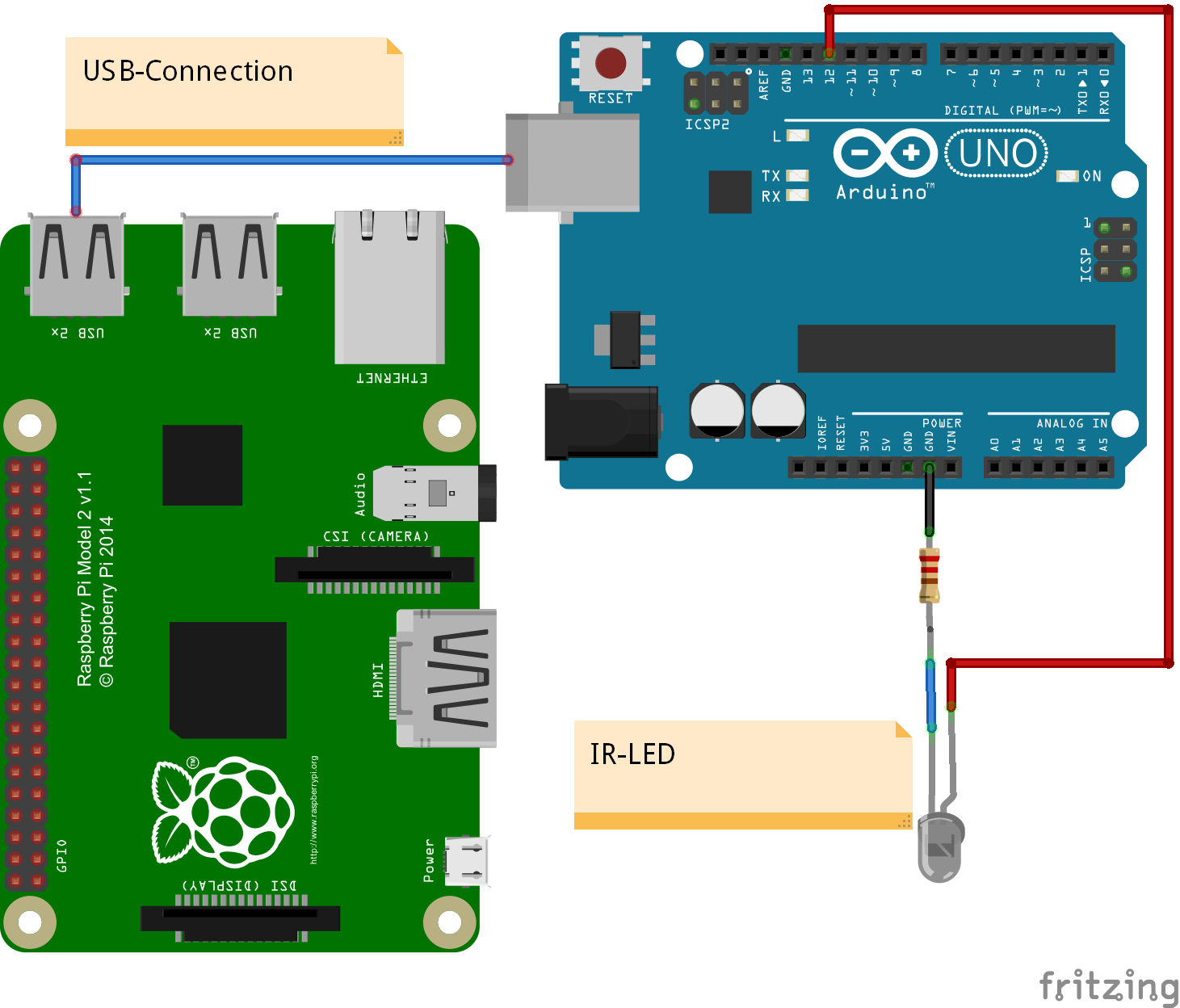
With a transistor like 2n2222 and a base resistor of 680Ohm, the power on the LED can be increased.
The scratch names used are configurable in configuration files. See the config file config/config_arduino_powerfunctions.xml
The arduino code for arduino IDE and configuration needed for scratchClient is in the scratchClient distribution.
Start arduino software, load arduino/power_functions/power_functions.ino and program it into the UNO.
Connect LED to Arduino
See the plan included above. This connection allows for currents up to 20mA. Most IR-LED support higher currents, but then a transistor is needed to drive the LED.
On raspberry, lookup /dev/tty* connections and configure the UNO serial device in config/config_arduino_powerfunctions.xml-File.
For windows, you see the COMn-Device used in deviceManager.
cd ~/scratchClient
python src/scratchClient -c config/config_arduino_powerfunctions.xml
There is a sample program in
scratch/arduinoUno/lego_powerfunctions.sb
The variables are connected to different channels, A and B are the two channels available on the LEGO receiver
The program takes the button input and controls the red LED with it.
The value from the potentiometer is used to set the pwm-rate and dim the green LED.
Twitter has an API which can be used by scratchClient. The adapter browses twitter for direct messages or by a hashtag and forwards these results to scratch.
Install python-twitter in python environment "sudo pip install python-twitter".
You need to obtain 'key' and 'secret' from twitter to access the API. Edit config/config_twitter.xml and insert values there.
Polling rate for twitter can be adjusted, but twitter.com imposes a rate limit. 60 sec are a good starting point.
It is configurable whether the adapter retrieves user message or searches messages for a term or both.
A properties file written by the adapter allows to retrieve only new messages. The messageId of last message read is persisted in this file. The file is in data folder, filename is configurable in config file.
Start scratchClient
cd ~/scratchClient
python src/scratchClient -c config/config_twitter.xml
A scratch sample is in
scratch/twitter/twitter.sb
Messages from twitter can arrive at a faster rate than scratch can process, or messages can be identical, which makes them indistinguishable for scratch. To handle this situation a protocol is implemented between the twitter adapter and scratch: all messages are queued inside the adapter. For each message, the text is places in a sensor variable 'text' and a 'textAvailable' event is published. When scratch receives this event, it processes the data and answeres with a 'textAcknowledge' event.
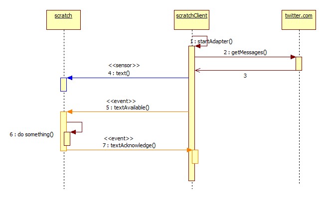
Openweathermap has an API which can be used by scratchClient. The adapter browses the api for weather data.
Install python module 'pyowm' in python environment
sudo pip install pyowm
sudo pip3 install pyowm
You need to obtain an API 'key' from http://openweathermap.org/appid to access the API. Edit the file config/config_openweatherapi.xml and insert values there.
In the configuration file, there is a default setting for the location. Adjust if needed.
Polling rate for openweathermap can be adjusted, but depending on key type there is a rate limit. 600 sec are a good starting point.
Start scratchClient
cd ~/scratchClient
python src/scratchClient -c config/config_openweatherapi.xml
Location can be set with a variable 'location' in scratch.
LEGO education offers a concept for primary schools which consists of hardware, software and educational patterns. The electronics part are
-
'Wedo 2.0 Smarthub', connected by Bluetooth Low Energy to a computer. Will be named 'hub' in this chapter.
-
'Wedo 2.0 Tilt Sensor', will be named 'tilt sensor' here.
-
'Wedo 2.0 Motion Sensor', will be named 'motion sensor' here.
-
'Wedo 2.0 Medium Motor', will be named 'motor' here.
It is important to name the devices with the WeDo 2.0 prefix, as the connector style is different from connectors used for other Lego products.
The hub offers two connectors, where the sensors or motors can be connected.
The hub connections are named as shown. This is important in 'advanced' setup.
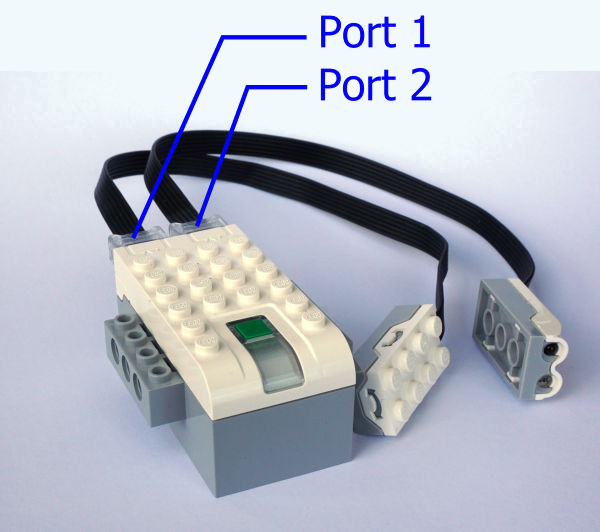
The software offered by Lego is an easy to use 'scratch style' IDE. The command set is very limited, appropriate to primary school. There is a 'while' block, but no decisions.
With the software, it is possible to use the sensors in their default mode.
There is a SDK available from Lego, which demonstrates the more advanced features of the hub and the sensors. Based on the SDK, the integration into scratchClient was developed.
-
Button. Used to start the bluetooth connection sequence.
During operation it acts as a push button which can be used by host software.
-
RGB LED. Used as status feedback. White flashing during bluetooth connection, blue when connected. Orange flashing in case of high current when a motor is blocked.
The scratchClient software - when connected - initiates a short red-green-blue animation and changes the color then to green.
The colors can be set by host software.
-
Piezo. Used as status feedback. Initiates some beeps while connecting.
Piezo can be used to play tones.
-
Voltage. Measures battery voltage.
The values in millivolts are available to host. Can not be set, of course.
-
Current. Measures current from the battery.
The values in milliamperes are available to host. Usual values are around 80 to 90 mA, some 100 mA higher when a motor is used.
-
Low Voltage Alert.
-
High Current Alert.
The hub also controls the connect/ disconnect of motors and sensors reports this to the host. The host can set operation mode for the devices. The hub can use notifications to report value changes.
There can be one or two motors connected to the hub. With WeDo software, these are operated 'in parallel', there is no possibility to address them separately.
The hub internally allows to address the motors based on the port to wich these are connected. scratchClient allows to operate two motors separately.
Motor can be powered by values [1..100] forward, [-1..-100] reverse. Value [0] is drift mode. A special value [127] is used for brake mode. The scratchClient adapter uses broadcast events for drift and brake.
Motion sensor offers two operation modes.
-
Mode 0, DETECT: Distance measurement. Values are from 0..9 for very near to very far which is prox 20cm.
The mode 0 is set as default.
-
Mode 1, COUNT: Counts the number of 'beam brake events'. Can be used to count parts passing by. Values are from 0..100. Counter can be reset by a broadcast event.
Tilt sensor offers three operation modes.
-
Mode 0, ANGLE: Gives two angle measurements in degrees -45.0 to +45.0.
-
Mode 1, TILT: Similiar to ANGLE, but value is restricted to tilt directions. This provides '0' for no tilt, and '3', '5', '7', '9' for each direction.
The mode 1 is set as default.
-
Mode 2, CRASH: Counts the number of crash events. This gives the number of bumps in x, y and z-direction. There is a reset signal available for the counter.
The adapter was devloped and tested on a Raspberry Pi 3 which provides a bluetooth 4 device. The software to operate is already included in raspbian. No special setup procedures have been needed to configure bluetooth.
The scratchClient adapter needs additional software to run. This is the python module needed for the bluetooth stack.
Install python module 'bluepy' for python environment.
sudo pip install bluepy
Do not automatically connect the hub with bluetooth. The scratchClient adapter will not be able to connect when other connections are already established.
The bluetooth connection can be build based on the MAC-address of the hub, or based on the device name.
For the connection based on MAC-address, edit the config file as follows:
        <!-- discover option by 'address' -->
        <parameter name='btle.policy' value='address' />
        <parameter name='btle.address' value='a0:e6:f8:6d:0e:67' />
Use this setup when there are many hubs around and one dedicated device needs to be connected.
For the connection based on device name, edit the config file as follows:
        <!-- discover option, by 'name' (needs root permission) -->

        <parameter name='btle.policy' value='name' />
        <parameter name='btle.name' value='LPF2 Smart Hub 2 I/O' />
Use this setup when only one hub is around, or the configuration effort is too high. Root peromission is needed to start scratchClient in this case. With many devices, the scratchClient adapter will connect with the first device found.
Start scratchClient.
Start scratch and establish 'remote sensor connection'.
Press the green button on the wedo2 hub. The LED will blink and there is an audible beep from the device. When connection is established, the LED turns to blue. After prox 3 to 5 seconds, the LED runs a short sequence red,green,blue and finally the LED remains green.
The connection is established.
With lego wedo2 education software, a subset of the hub's features can be used. It is assumed, that only one motor or only one sensor of a type are connected. It is not important on which connector the devices are plugged in.
Motion-Sensor mode is 'distance'. Values provided are '0.0' for very close and '9.0' for 'very far away.'
Tilt-Sensor mode is 'tilt'.
To operate the hub in this mode, a 'basic' setup configuration is provided
config/config_wedo2_basic.xml
.
This basic configuration is a subset of the available options of the adapter.
In the configuration, the 'strict' parameter is set to 'false'. This ignores the position of a connected sensor/actor.
<parameter name='mode.strict' value='false' />
Typically, a motor is adressed by 'motor'.
When two motors are connected, these will operate in parallel. But two sensors of one type will produce wrong data.
Start scratchClient in basic mode.
cd ~/scratchClient
 sudo python src/scratchClient.py -c config_wedo2_basic
The scratchClient monitoring gives a graphical view of the inputs and outputs of an adapter configuration.
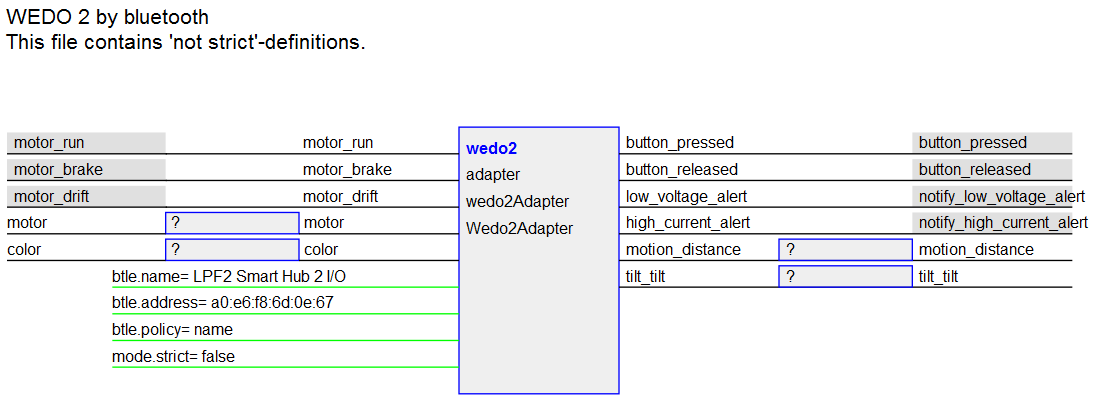
The mode set values are removed from this config file. Piezo commands are not used. Voltage, current values are removed. This configuration is close to the scenario used in WeDo software.
In advanced operation mode it is possible to handle the connected motor or sensors individually. Two motors can be controlled separately, or two same sensors can be read.
To operate the hub in this mode, an 'advanced' setup configuration is provided
config/config_wedo2_advanced.xml
.
This advanced configuration is a subset of the available options of the adapter.
The motor and sensor values have names with the port indicator '1', '2' included. For example the motion sensor values are named 'motion1_distance', 'motion2_distance'.
For the sensors, the values used are depending on the mode set. For the motion sensor, there is a 'motion1_distance' and a 'motion1_count' sensor value. When mode is changed, the last value reported in other sensor variables is not reset or changed.
In the configuration, the 'strict' parameter is set to 'true'. This allows to address sensor/actor by port position.
<parameter name='mode.strict' value='false' />
Typically, a motor is adressed by 'motor1' or 'motor2'.
Start scratchClient in advanced mode.
cd ~/scratchClient
 sudo python src/scratchClient.py -c config_wedo2_advanced
The scratchClient monitoring gives a graphical view of the inputs and outputs of an adapter configuration.
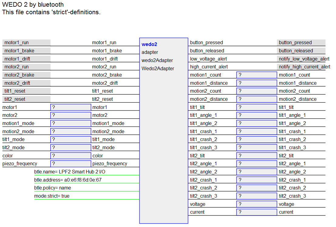
A full blown config file with all options is available. The main purpose is for test and development.
To operate the hub in this mode, an 'complete' setup is provided
config/config_wedo2_complete.xml
.
In the configuration, the 'strict' parameter is set to 'true'. This allows to address sensor/actor by port position.
<parameter name='mode.strict' value='true' />
Start scratchClient in complete mode.
cd ~/scratchClient
 sudo python src/scratchClient.py -c config_wedo2_complete
The scratchClient monitoring gives a graphical view of the inputs and outputs of an adapter configuration.
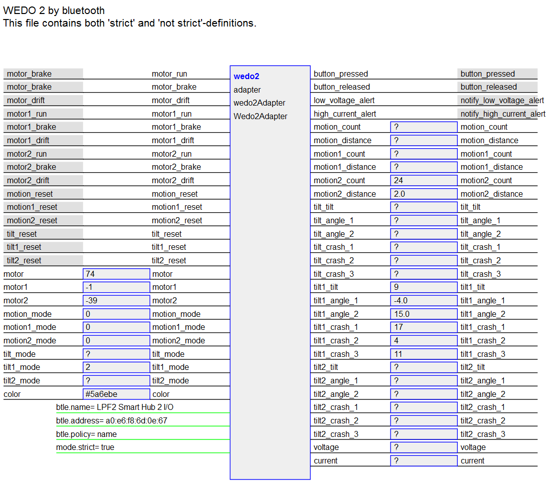
A sample scratch program is provided in
scratch/wedo2/wedo2_sample.sb
.
Use the 'green flag' to start the program.
This scratch program can be used with basic, advanced or full configuration files.
In the status line, the green sprite displays the button press events.
Alerts for voltage or current should be green. When alerts arrive, these turn to red and change to orange 5 secs later.
The current screen name is displayed.
The 'prev'- and 'next'-Buttons are used to navigate to the other screens. When a wedo2-hub is connected, the green button on the hub is scrolling the screen too.
|
The scratch motor blocks are NOT related to the WDEO2-Adapter and can't be used to control the wedo2-motor. |
There are error messages during startup of the adapter like
2017-03-16 23:34:53,987 - adapter.wedo2Adapter - ERROR - notify_data, no service for port 6
2017-03-17 00:31:03,768 - adapter.wedo2Adapter - ERROR - motion, data not parsed 04 02 00 00 00 40 03 2d 7a b4 42
These error messages are only important if they occurr after a longer time of operation. Immediately after startup they are caused by a 'race condition' in the adapter code and no problem.
HC-SR04 is a quite inexpensive ultrasonic distance sensor. The pulse output can be measured using pigpio daemon and python library.
The device needs a trigger connection and an echo connection. As the operating voltage for the device is 5V, there is the need for voltage adjustment for the echo line. Use a voltage divider or level shifter.
The GPIO pins used are configured in the config file. Any pins can be used.
Multiple sensors can be configured.
Installation
The python library for pigpio access needs to be installed.
sudo apt-get install python-pigpio
The daemon code is available in raspbian (2016-08-19).
Start Daemon
The daemon can be started by raspi-config. Or start by
sudo pigpiod
A basic configuration is is
config/config_hcsr04_pigpiod.xml
.
Start scratchClient.
cd ~/scratchClient
python src/scratchClient.py -c config_hcsr04_pigpiod
The values transferred to scratch are 'time' in seconds. To calculate the distance use the formula
distance [cm] = time [s] * 340 [m/s] / 2 * 100 [cm /m])
The speed of sound in air is assumed to be 340 [m/s], which changes with temperature.
Pimoroni offers a 6 digit 7*5 dot display "MICRO DOT PHAT" with 3 IS31FL3730 chips. The adapter was written using code from pimoroni library.
Installation needs extra libraries numpy and smbus
sudo pip install numpy
sudo apt-get install python-smbus
sudo pip3 install numpy
sudo apt-get install python3-smbus
I2C-Bus needs to be enabled.
Hello-world-display:
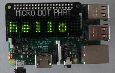
The character to font translation does not contain all possible chars. If needed, look into the adapter code which has a 'pixel'-graphics setup capability. Example:
    font_5_7[ '¿'] = """
          :  *  :
          :     :
          :  *  :
          :  *  :
          : *   :
          :*   *:
          : *** :
    """
Just add chars as needed.
There is a sample config file in config/config_microdotphat.xml.
Pimoroni offers a 7*17 LED display "SCROLL PHAT HD" with an IS31FL3731 chip. The adapter code was written using code from pimoroni library.
The adapter is primarily used as pixel output. Text output is possible, but limited to a few characters only.
The command variable can be used to issue various pixel set commands:
-
'
clear' -
'
clear;x;y' clear pixel -
'
clear;x;y;bright' set pixel to brightness -
'
pixel;x;y' set pixel to default brightness -
'
pixel;x;y;bright' set pixel to brightness -
'
box;x;y;width;height' set area to default brightness -
'
box;x;y;width;height;bright' set area to brightness
x is pixel position [0..16]
y is pixel position [0..6]
width is box width [1..17]
height is box height [1..7]
bright is brightness [0.0..1.0]
Separator is ';'.
Wrong commands are silently ignored.
Scratch does not send out a broadcast message to remote sensor network on each variable set commands when in one block. Commands need to be separated by a wait(0) block.
Installation needs extra libraries numpy and smbus
sudo pip install numpy
sudo apt-get install python-smbus
sudo pip3 install numpy
sudo apt-get install python3-smbus
. I2C-Bus needs to be enabled.
The character to font translation does not contain all possible chars. If needed, look into the adapter code which has a 'pixel'-graphics setup capability. Example:
    font_5_7[ '¿'] = """
          :  *  :
          :     :
          :  *  :
          :  *  :
          : *   :
          :*   *:
          : *** :
    """
Just add chars as needed.
There is a sample config file in
config/config_scrollphatht.xml
.
There is a sample scratch script in
scratch/scrollphathd/scroll_phat_hd.sb
.
On Raspberry Pi, raspbian, there is minecraft in a local mode-version available. For this edition, a python api exists.
User guide is www.raspberrypi.org/learning/getting-started-with-minecraft-pi
The API is described in stuffaboutcode.com/p/minecraft-api-reference
A sample scratch script is in
scratch/minecraft/minecraft.sb
scratchClient allows to build configurations from adapters and adjust these to devices. A sample is pi2go, a two wheel robot with sensors, actors of different type.
There is a web based user interface for the tool. By default, the scratchClient opens the port only for local connections. When remote access is needed, this needs to be enabled by command line switch 'guiRemote'.
The url in browser is for local access http://localhost:8080
For remote access, you need to have the hostname in the network, or the ip-address of the machine. http://[hostname]:8080
The functionality is
-
show config file
-
display graphical view of adapters
-
monitor events
-
trigger events
-
set values
The adapter view receives updates from scratchClient. When broadcasts arrive, the connectors are highlighted. Values change are displayed. Most current events are listed on screen in a text list.
Broadcasts (input or output) can be stimulated by clicking to the connectors. Input broadcasts are sent to the adapter, output broadcasts are sent to scratch.
Values can be edited and send. Click on the connector, an input box will open and values are sent when enter key is pressed.
Input values are sent to the adapter, output values are sent to scratch. The web interface is build based on configuration.
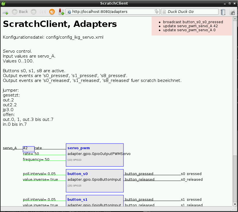
The sample screen shot shows a servo adapter and two button adapters. 'servo_A' is a value sent from scratch to the adapter. Double click in this name opens an editor window for the value. 's0_pressed' is a broadcast sent from the button-adapter to scratch. Double clicking this name sends the broadcast to scratch.
The following installation procedure is for the impatient people. Open a terminal and execute the following lines.
cd ~
wget -O scratchClient.tar.gz http://heppg.de/download/scratchClient/scratchClient.tar.gz
tar xzf scratchClient.tar.gz
chmod +r -R scratchClient/

sudo apt-get update
sudo apt-get install python-pip  python-dev  python-smbus
sudo apt-get install python3-pip python3-dev python3-smbus
sudo pip  install tornado mako==1.0.6 spidev pyserial intelhex
sudo pip3 install tornado mako==1.0.6 spidev pyserial intelhex
The install steps are explained in more detail in the following sections.
The following sections guide through the installation steps.
There are a few operating system packages and a few python modules needed.
When installing new packages, it is generally a good idea to have current versions of the packages available. For this, the 'apt-get update' is used.
sudo apt-get update
sudo apt-get install python-pip  python-dev  python-smbus
sudo pip  install tornado mako==1.0.6 spidev pyserial intelhex
If you want to use python3, then the following commands are needed
sudo apt-get update
sudo apt-get install python3-pip python3-dev python3-smbus
sudo pip3 install tornado mako==1.0.6 spidev pyserial intelhex
scratchClient is a python program and requires no special compile step. The files are unpacked to a local directory.
The chmod command ensures that the files are readable also for other users.
On the download page, there are usually some version hints. download page
The files are downloaded to user home directory, usually /home/pi.
cd ~
wget -O scratchClient.tar.gz http://heppg.de/download/scratchClient/scratchClient.tar.gz
tar xzf scratchClient.tar.gz
chmod +r -R scratchClient/
Verification of installation.
You should have /home/pi/scratchClient/src/scratchClient.py and other files.
Start scratchClient, preferred with python3
cd ~/scratchClient
python3 src/scratchClient.py -h
Expected output is a list of command line options.
Some devices are connected by SPI. When such devices are needed, SPI drivers are needed.
On raspberryPi, you can enable SPI by using raspi-config.
sudo raspi-config
To install it manually, edit raspi-blacklist
sudo leafpad /etc/modprobe.d/raspi-blacklist.conf
The following entry must be available:
#blacklist spi-bcm2708
Delete all other lines which contain spi-bcm2708
Reboot recommended.
Validation
Validate installed drivers. 'lsmod' lists installed drivers.
lsmod | grep -e spi_bcm2708
For using I2C, additional software needs to be installed.
sudo apt-get install python-smbus
On raspberryPi, you can enable I2C by using raspi-config.
sudo raspi-config
In addition to this driver, there is i2c-dev needed. Starting this manually is
sudo modprobe i2c-dev
To manually enable the I2C-Driver: edit raspi-blacklist
sudo leafpad /etc/modprobe.d/raspi-blacklist.conf
The following entry must be available, or no entry at all:
#blacklist i2c-bcm2708
Delete all other lines which contain i2c-bcm2708
In /etc/modules , add a line with i2c-dev. This makes i2c-dev permanent.
Reboot recommended.
Validation Validate installed drivers. 'lsmod' lists installed drivers.
lsmod | grep -e i2c
Result should contain
i2c_dev                 6709  2
i2c_bcm2708             6200  0
In folder /dev, there is a directory /dev/i2c-1 available.
It is recommended to install
sudo apt-get install i2c-tools
In these tools, i2cdetect helps to find out connected devices with their adress.
When using the text to speech adapter 'festival', the package 'festival' is needed.
sudo apt-get install festival
When using the text to speech adapter 'pico2wave', the package 'pico2wave' is needed.
sudo apt-get install libttspico-utils
For DMA based adapters, a DMA-library is needed. In scratchClient releases prior to 2016-01-02, the RPIO.PWM-library was used. As this RPIO.PWM-library did not support Raspberry Pi2 or Pi2, a local patch 'RPIO2.PWM' was created.
This RPIO2.PWM library needs additional installation
cd ~/scratchClient/RPIO2
sudo sh install.sh
Custom config files can be placed on disk where appropriate.
The tool encourages to use the configuser directory ~/scratchClient/configuser.
The install procedures do not wipe this directory. Be sure to backup regularily.
The supplied config files samples are in ~/scratchClient/config.
In scratch, enable the 'remote network connection'. This is needed once for a project; this setting is persisted in the project file. Start with (user pi)
cd ~/scratchClient
sudo python src/scratchClient.py -config [config_file_name.xml]
For gpio access, SPI, I2C-adapters, it is usually required to run the program with root permissions. Some adapters run with 'normal' permissions, e.g. the text-to-speech adapter, websocket adapters or alike.
scratch needs to be started separately. Create a shell script if you need both programs scratchClient and scratch to be started with one command.
The code generates a 'scratchClient.pid'-File, which may remain in base directory. There for, start up in a dedicated home directory (~/scratchClient) is recommended.
|
On one machine, the process may only be started once. If the process starts up, but quits after some 30 to 60 sec, then possibly another instance is running. |
Use command line '-h' to see options.
cd ~/scratchClient
python src/scratchClient.py -h

-host <ip>           Scratch Host ip or hostname, default 127.0.0.1
-port <number>       Port number, default 42001

-c <configfile>
-config <configfile> Name of config xml-file, default config/config.xml
                     There is a lookup strategy used (add xml extension when needed,
                     check if file exists literally. Then try to find a matching file
                     in configuser dir, next in config-dir. Try to add 'config_' to
                     filename also.

-C <configfile>      Name of config xml-file, default config/config.xml
                     There is NO lookup strategy used, only literal.

-gpioLib             set the gpiolibrary, default 'RPi_GPIO_GPIOManager'
                     deprecated

-singletonPID        when multiple instances are running, report other instance and
                     terminate
-singletonIPC        when multiple instances are running, terminate other instance
                     used port 42003 (default from 2017-02-14)
-singletonNONE       no singleton policy applied. For debug only

debug and test switches

-validate            Validate config and terminate.

-h
-help                print command line usage and exit
-v                   verbose logging
-d                   debug logging
-license             print license and exit.
-changes             print changes list  and exit.
-version             print version and exit.
Most of the commands are quite self-explaining. If you want to see more information on screen, use verbose switch. Debugging switch shows even more, but then logging uses a lot of CPU.
config:
For config file lookup, there is a lookup policy available. The first file found wins the game:
add xml extension when not available.
-
check file name given literally.
-
look in ./userconfig directory, then in ./config/
add prefix 'config_' to filename if no path is given.
With this policy, file names can be abbreviated.
host:
if scratch is located on a different computer, then give the target address here.
port:
generally not needed to use a different port.
nogui:
does not start the web app server inside scratchClient. Less memory usage.
guiRemote:
allows remote access to web gui.
validate:
check the config file for correctness.
singleton
It is needed that scratchClient is running only once on one computer. Till 2017-02-14, the policy used was a pid-file in installation directory and stop when another instance was already running.
From 2017-02-14, there is another policy 'IPC' which terminates the earlier started instance. This singleton manager uses socket 42003 to connect to an already running instance and requests to terminate.
To use the IPC based policy, add -singletonIPC to the command line or leave empty.
To use the legacy PID based policy, add -singletonPID to the command line.
Stop with ctrl-c in console. Takes up to a minute till all background threads quit.
If for any reason the code refuses to quit, get the processId and kill the process
sudo ps -ef | grep python
sudo kill -9 [processId]
Some common problems in running scratchClient are, that no sensor inputs are arriving in scratch. Check the following list for possible problems.
-
is scratchClient started? It might stop running due to problems in configuration file. Check console log for details.
-
is scratchClient started? It might stop running due to a previous instance leaving a scratchClient.pid-File. Delete this file.
-
multiple instances of scratchClient started ? Check with
ps -ef | grep pythonand stop other instances withkill -9 <pid> -
multiple instances of scratch ? Only one instance of scratch is allowed having the remote sensor protocol started. Stop other instances.
Scratch will read inputs from scratchClient faster than these are processed internally. The effect is that scratch is displaying old data. In this case, decrease update rates of polling sensors and work on performance of scratch code.
pi@raspberrypi:~/scratchClient $ python src/scratchClient.py -config config/config_arduino_uno.xml
Traceback (most recent call last):
  File "src/scratchClient.py", line 151, in <module>
    import server.scratchClientServer
  File "/home/pi/scratchClient/src/server/scratchClientServer.py", line 33, in <module>
    import cherrypy
ImportError: No module named cherrypy
pi@raspberrypi:~/scratchClient $
The installation of cherrypy is missing. Runsudo pip install cherrypy routes mako ws4py spidev
When auto start for scratch is needed, there are things to execute
-
start scratch into presentation mode
-
enable remote connections (without user interaction)
-
issue a 'green flag' event.
Starting scratch and scratchClient can be in any order. Starting does not need to be manual, but can be from init.d or other
Starting scratch into presentation mode can be done on RaspberryPi by adding the 'presentation' keyword to the command line.
scratch presentation [scriptname]
When starting scratch from a background process then add the X display
scratch presentation [scriptname] -display :0
This will be needed when you 'remote login' to a linux system.
Starting with 'presentation'-flag also issues a green-flag-event.
When a project uses remote connection, this is stored in the project file and enabled again when project is reloaded. Unfortunately, there is some user interaction needed to enable it.
In newer scratch releases for raspberry (e.g. 2015-11-11), there is a config file setting which bypasses this dialog.
remoteconnectiondialog = 0
Look for file home/pi/.scratch.ini and add this statement. If this file is not available, just create it.
|
Files starting with '.' are hidden files in linux. With filemanager, enable 'show hidden files' in order to see this file. |
ScratchClient and scratch usually run on same machine, but other scenario are possible.
In general, scratchClient and scratch will run on same machine.

No special command line switches are needed to support this scenario.
scratchClient and scratch can run on different machines. I use this scenario, when debugging scratch code on a more performant machine than a raspberry pi.

When starting scratchClient, use the '-host'-command line parameter and add the ip-address (or hostname) of the machine where scratch is located. Of course, these two machines need to be connected by a network.
scratchClient and scratch can run on different machines. The browser used to look into the monitoring gui of scratchClient can be used from a third machine.

When starting scratchClient, use the '-host'-command line parameter and add the ip-address (or hostname) of the machine where scratch is located. Use '-guiRemote' to allow remote access for browser. Of course, these machines need to be connected by a network.
| Module | Port | computerA | computerB | computerC |
|---|---|---|---|---|
| scratch | 42001 | out | in | |
| browser | 8080 | in | out |
When you need a new adapter, not provided in the list. Add a new file to Directory 'adapter' named myadapter.py (choose the name according to the functionality). Place a class there named MyAdapter (again, choose your functional name). Derive it from adapter.Adapter, and place __init__ and command methods, as well as the output methods. Produce the xml-configuration for this, and give it a try. Testing new Adapters: add your adapter config to an xml-file, start the code in simulation mode with gui. If configurationManager reads the config successfully, you will be able to place commands and values to the input side, and see what happens to the simulated gpio.
Then stop and restart in real live mode. This will attach the gpios and drive whatever is attached there.
Using other gpio-driver as Rpi.GPIO
There are people using Wiring, or other python libraries to access Gpio on the pi. Copy RPiGpio.py, which is a wrapper for the RPI-GPIO, and copy to a 'MyGPio.py'-File. In the new file, modify the imports and the method content to whatever is needed to run your library. On the command line, use -gpio [yourGpioPath], for this example it is „adapter.MyGpio“. Generally, as this is running as a standalone client, with most probably no other code in parallel, this will be rarely needed.
GPIO names used are configurable in config/portMapping.xml. This file maps the gpioNumbers from BCM numbering to other names, either GPIO-, PIN-numbers or whatever else needed. GPIO08 is GPIO numbering in BCM style.
<port gpioNumber='8' name='GPIO08' />
IKG.IO.3 is used for a special adapter-board.
<port gpioNumber='18' name='IKG.IO.3' />
Pin header names. The version-ambiguities are resolved by appending the version number to the port name
    <port gpioNumber='0' name='P1-03V1' />
    <port gpioNumber='2' name='P1-03V2' />
The mapped names can be used in config files.
The code is developed and tested in python 2.7.3.
Some checks have been performed with python3 and pypy. If there are problems in these environment, then please let me know.
External libraries are
-
Rpi.GPIO 0.5.3a or 0.5.4a
-
RPIO
-
cherrypy 3.2.4 for the web gui
-
route
-
mako
SPI, I2C, TextToSpeech as needed.
Scratch is Version 1.4, as there the remote sensor protocol is available. As of now (juli 2013), I do not know about plans to have this sensor network in scratch 2.0.
GNU General Public License
Copyright (C) 2013, 2014 Gerhard Hepp
This program is free software; you can redistribute it and/or modify it under the terms of the GNU General Public License as published by the Free Software Foundation; either version 2 of the License, or (at your option) any later version.
This program is distributed in the hope that it will be useful, but WITHOUT ANY WARRANTY; without even the implied warranty of MERCHANTABILITY or FITNESS FOR A PARTICULAR PURPOSE. See the GNU General Public License for more details.
You should have received a copy of the GNU General Public License along with this program; if not, write to the Free Software Foundation, Inc., 51 Franklin St, Fifth Floor, Boston, MA 02110, USA
Technical description of adapters, input, output values and events and config snippets.
AD-Interface for ADS1015.
AD-Interface for ADS1015.
Class
adapter.i2cAdapter.ADC_ADS1015_Input
Output Values
| adc |
ADC value |
Parameter (mandatory)
| adc.channel |
the adc-channel [0..3] |
|
| i2c.address |
address is '0x48' for adafruit ADS1015-breakout |
|
| i2c.bus |
bus is '1' for RPi Release 2 |
|
| poll.interval |
poll interval in secs, e.g. 0.05 |
Parameter (optional)
| adc.pga |
Programmable Gain Amplifier setting, default 4096, [256, 512, 1024, 2048, 4096, 6144] |
|
| adc.sps |
Sample Per Second, default 250 [ 128, 250 , 490, 920, 1600, 2400, 3300 ]. For scratch, fast rates are not needed. |
Sample configuration
    <adapter class='adapter.i2cAdapter.ADC_ADS1015_Input'  name='adc_A2'>
        <description>ADC-Value from ADS1015 (single ended)</description>
        <output_value name='adc'>
            <sensor name='adc_A2'/>
        </output_value>

        <parameter name='poll.interval' value='0.05' />

        <!-- bus is '1' for RPi Release 2 -->
        <parameter name='i2c.bus' value='1' />

        <!-- address is '0x48' for adafruit ADS1015 -->
        <parameter name='i2c.address' value='0x48' />

        <parameter name='adc.channel' value='2' />
        <!-- optional -->
        <parameter name='adc.sps'  value='250' />
        <parameter name='adc.pga'  value='6144' />

    </adapter>
PCF8591-Adapter, 4 channel ADC and 1 channel DAC.
The adapter can read 4 channels in sequence; the DAC output is optional.
Class
adapter.i2cAdapter.ADC_DAC_PCF8591
Output Values
Parameter (mandatory)
| dac.enable |
dac enabled. |
|
| i2c.address |
Base address, int or hex. |
|
| i2c.bus |
Bus snumber, usually 1 on RPi. |
|
| poll.interval |
poll rate. |
Parameter (optional)
| average.cnt |
Number of measurements in an average. 1..10 are good values. |
|
| average.enable |
poll rate. |
Sample configuration
    <adapter class='adapter.i2cAdapter.ADC_DAC_PCF8591' name='4-channel Light sensor'>
        <description>4 channel light sensor.</description>

        <output_value name="adc_0">
             <sensor name="light_D5"/>
        </output_value>
        <output_value name="adc_1">
             <sensor name="light_D6"/>
        </output_value>
        <output_value name="adc_2">
             <sensor name="light_D8"/>
        </output_value>
        <output_value name="adc_3">
             <sensor name="light_D9"/>
        </output_value>

        <!-- bus is '1' for RPi Release 2 -->
        <parameter name='i2c.bus' value='1' />

        <!-- Depending on address select, the bus address is
             '0x40' for all address lines low.
             -->
        <parameter name='i2c.address' value='0x48' />
        <parameter name='dac.enable' value='false' />
        <parameter name='poll.interval' value='0.1' />

        <parameter name='average.enable' value='true' />
        <parameter name='average.cnt' value='5' />
    </adapter>
ADC interface MCP3008, 8 channel ADC
Interface to adc MCP3008, 10bit.
Class
adapter.adc_zone.ADC_MCP3008_10_Input
Output Values
| adc |
value int 0..1023 |
Parameter (mandatory)
| adc.channel |
adc channel (0,7). |
|
| poll.band |
deadband zone +- last value, only if new value is outside this band it is reported. |
|
| poll.interval |
poll rate in seconds, default 0.05. |
|
| spi.bus |
bus number, 0, 1 |
|
| spi.device |
spi bus selector, 0, 1 |
Sample configuration
    <adapter class='adapter.adc.ADC_MCP3008_10_Input'  name='adc_A'>

        <description>ADC-Value</description>

        <output_value name='adc'>
            <sensor name='adcA'/>
        </output_value>

        <parameter name='poll.interval' value='0.066' />
        <parameter name='poll.band' value='2' />
        <parameter name='spi.bus' value='0' />
        <parameter name='spi.device' value='0' />
        <!-- channel 0..7 -->
        <parameter name='adc.channel' value='7' />
    </adapter>
ADC interface MCP3202
Interface to adc MCP3202, 10bit.
Class
adapter.adc.ADC_MCP3202_10_Input
Output Values
| adc |
value 0..1023 |
Parameter (mandatory)
| adc.channel |
adc channel (0,1). |
|
| poll.interval |
poll rat ein seconds, default 0.05. |
|
| spi.bus |
bus number, 0, 1 |
|
| spi.device |
spi bus selector, 0, 1 |
Sample configuration
    <adapter class='adapter.adc.ADC_MCP3202_10_Input'  name='adc_A'>

        <description>ADC-Value</description>

        <output_value name='adc'>
            <sensor name='adcA'/>
        </output_value>

        <parameter name='poll.interval' value='0.066' />
        <parameter name='spi.bus' value='0' />
        <parameter name='spi.device' value='0' />
        <parameter name='adc.channel' value='0' />
    </adapter>
ADC interface MCP3202, zone value mapping
Interface to adc MCP3202, 10bit. The input values are mapped to zones.
Zone values can be used for threshold values, e.g. 0..511 to 0, 512..1023 to 1023.
Zone values can be used for value mapping, e.g. 0..99 to 'left', 100..923 to 'middle', 924..1023 to 'right'.
Class
adapter.adc_zone.ADC_MCP3202_10_Zone_Input
Output Values
| adc |
value int values or string |
Parameter (mandatory)
| adc.channel |
adc channel (0,1). |
|
| poll.interval |
poll rate in seconds, default 0.05. |
|
| spi.bus |
bus number, 0, 1 |
|
| spi.device |
spi bus selector, 0, 1 |
Sample configuration
    <adapter class='adapter.adc_zone.ADC_MCP3202_10_Zone_Input'  name='adc_A_Zone'>

        <description>ADC-Value</description>

        <output_value name='adc'>
            <sensor name='adcA_zone'/>
        </output_value>

        <extension>
        <zone from='0' to='99' value='left'/>
        <zone from='100' to='923' value='middle'/>
        <zone from='924' to='1023' value='right'/>
        </extension>

        <parameter name='poll.interval' value='0.066' />
        <parameter name='spi.bus' value='0' />
        <parameter name='spi.device' value='0' />
        <parameter name='adc.channel' value='0' />
    </adapter>
ADC interface MCP3202
Interface to adc MCP3202, 12bit.
Supports averaging (filter).
Class
adapter.adc.ADC_MCP3202_12_Input
Output Values
| adc |
value 0..4095 |
Parameter (mandatory)
| adc.channel |
adc channel (0,1). |
|
| filter.depth |
0,1: no filtering; 2..10: filtering |
|
| poll.interval |
poll rat ein seconds, default 0.05. |
|
| spi.bus |
bus number, 0, 1 |
|
| spi.device |
spi bus selector, 0, 1 |
Sample configuration
    <adapter class='adapter.adc.ADC_MCP3202_12_Input'  name='adc_A'>

        <description>ADC-Value</description>

        <output_value name='adc'>
            <sensor name='adcA'/>
        </output_value>

        <parameter name='filter.depth' value='8' />

        <parameter name='poll.interval' value='0.066' />
        <parameter name='spi.bus' value='0' />
        <parameter name='spi.device' value='0' />
        <parameter name='adc.channel' value='0' />
    </adapter>
Drives a bipolar stepper motor.
Bipolar steppers need four half bridge drivers, e.g. LM293
Class
adapter.stepper.BipolarStepper
Input Events
| startMotor |
not used |
| stopMotor |
not used |
Input Values
| speed |
time between steps. The smaller, the faster the motor will run. |
|
| target |
Target is 'step points' on an absolute scale. |
Sample configuration
   <adapter class='adapter.stepper.BipolarStepper' name='stepper'>

        <description>stepper control</description>

        <gpio port='GPIO25' alias='br0.0'>
            <default dir='OUT' pull='PUD_OFF'  />
            <active dir='OUT' pull='PUD_OFF'/>
        </gpio>
        <gpio port='GPIO24' alias='br0.1'>
            <default dir='OUT' pull='PUD_OFF'  />
            <active dir='OUT' pull='PUD_OFF'/>
        </gpio>

        <gpio port='GPIO23' alias='br1.0'>
            <default dir='OUT' pull='PUD_OFF'  />
            <active dir='OUT' pull='PUD_OFF'/>
        </gpio>
        <gpio port='GPIO18' alias='br1.1'>
            <default dir='OUT' pull='PUD_OFF'  />
            <active dir='OUT' pull='PUD_OFF'/>
        </gpio>

        <gpio port='GPIO22' alias='en0'>
            <default dir='OUT' pull='PUD_OFF'  />
            <active dir='OUT' pull='PUD_OFF' default='high' />
        </gpio>
        <gpio port='GPIO27' alias='en1'>
            <default dir='OUT' pull='PUD_OFF'  />
            <active dir='OUT' pull='PUD_OFF'  default='high' />
        </gpio>

        <input name='startMotor'>
            <broadcast name='startMotor'/>
        </input>

        <input name='stopMotor'>
            <broadcast name='stopMotor'/>
        </input>

        <input_value name='speed'>
            <variable name='speed'/>
        </input_value>

        <input_value name='target'>
            <variable name='target'/>
        </input_value>

    </adapter>
USB adapter for blink-device.
'blink(1)' is a small USB-device with two LED. See https://blink1.thingm.com/
The color commands do not use the device timed fade.
Needs installation of pyusb.
Class
adapter.usbAdapter.Blink_Adapter
Sample configuration
   <adapter class='adapter.usbAdapter.Blink_Adapter'  name='blink_1'>
        <description></description>

        <!--  led_0 is 'all led' -->
        <input_value name='led_0'>
            <variable name='led_all'/>
            <variable name='led_0'/>
        </input_value>

        <input_value name='led_1'>
            <variable name='led_1'/>
        </input_value>

        <input_value name='led_2'>
            <variable name='led_2'/>
        </input_value>

    </adapter>
Reading capacitive touch from CAP1208.
The code for this adapter was written based on code from pimoroni.
The chip is used in explorer hat pro. The numbering on the pcb is different from the chip internal numbering.
Class
adapter.cap1xxxAdapter.CAP1208Adapter
Output Event
| s0_pressed |
s0 activated |
| s0_released |
s0 released |
| s1_pressed |
s0 activated |
| s1_released |
s1 released |
| s2_pressed |
s0 activated |
| s2_released |
s2 released |
| s3_pressed |
s0 activated |
| s3_released |
s3 released |
| s4_pressed |
s0 activated |
| s4_released |
s4 released |
| s5_pressed |
s0 activated |
| s5_released |
s5 released |
| s6_pressed |
s0 activated |
| s6_released |
s6 released |
| s7_pressed |
s0 activated |
| s7_released |
s7 released |
Parameter (mandatory)
| i2c.address |
address is '0x48' for adafruit ADS1015-breakout |
|
| i2c.bus |
bus is '1' for RPi Release 2 |
|
| poll.interval |
poll interval in secs, e.g. 0.05 |
Sample configuration
 <adapter class='adapter.cap1xxxAdapter.CAP1208Adapter' name='cap'>
        <description>Capacitive sensors</description>

        <output name='s0_pressed'>
            <broadcast name='cap_5_pressed' />
        </output>
        <output name='s0_released'>
            <broadcast name='cap_5_released' />
        </output>

        <output name='s1_pressed'>
            <broadcast name='cap_6_pressed' />
        </output>
        <output name='s1_released'>
            <broadcast name='cap_6_released' />
        </output>

        <output name='s2_pressed'>
            <broadcast name='cap_7_pressed' />
        </output>
        <output name='s2_released'>
            <broadcast name='cap_7_released' />
        </output>

        <output name='s3_pressed'>
            <broadcast name='cap_8_pressed' />
        </output>
        <output name='s3_released'>
            <broadcast name='cap_8_released' />
        </output>

        <output name='s4_pressed'>
            <broadcast name='cap_1_pressed' />
        </output>
        <output name='s4_released'>
            <broadcast name='cap_1_released' />
        </output>

        <output name='s5_pressed'>
            <broadcast name='cap_2_pressed' />
        </output>
        <output name='s5_released'>
            <broadcast name='cap_2_released' />
        </output>

        <output name='s6_pressed'>
            <broadcast name='cap_3_pressed' />
        </output>
        <output name='s6_released'>
            <broadcast name='cap_3_released' />
        </output>

        <output name='s7_pressed'>
            <broadcast name='cap_4_pressed' />
        </output>
        <output name='s7_released'>
            <broadcast name='cap_4_released' />
        </output>

        <parameter name='poll.interval' value='0.075' />

        <!-- bus is '1' for RPi Release 2 -->
        <parameter name='i2c.bus' value='1' />
        <parameter name='i2c.address' value='0x28' />
    </adapter>
Remote communication adapter.
Needs the scratchCommunicationServer to be started.
For the configuration, an adapter-specific syntax is used.
There is a limit on inputs, max 32 commands are supported.
Class
adapter.remote.CommunicationAdapter
Parameter (mandatory)
| group |
The scratchCommunicationServer can handle different (isolated) groups. Only scratchClients in same group can communicate. |
|
| server |
IP-Address of computer where scratchCommunicationServer is located. |
Sample configuration
   <adapter class='adapter.remote.CommunicationAdapter' name='communication_adapter'>

        <!-- Adapter uses native Syntax -->
        <description>Remote communication adapter. </description>

        <extension>
            <!--  these commands are received from scratch and forwarded to a remote attached scratchClient -->
            <remote type='forward'>
	            <broadcast name='command_B'/>
	        </remote>

	        <!--  these commands are received from a remote attached scratchClient and sent to local scratch -->
	        <remote type='receive'>
	            <broadcast name='command_A'/>
	        </remote>
        </extension>
        <parameter name="group" value="groupA"  />
        <parameter name="server" value="192.168.2.108" />

    </adapter>
DMA based PWM adapter.
Needs installation of RPIO2-package.
Supports 0..100% pwm signals.
Class
adapter.dma_pwm.DMA_PWM
Input Values
| rate |
pwm rate [0..100] |
Parameter (mandatory)
Sample configuration
  <adapter class='adapter.dma_pwm.DMA_PWM'  name='rgb_B'>
        <description>Sample DMA PWM, needs installation of RPIO2-package.</description>

        <gpio port='IKG.IO.5'>
            <default dir='OUT'  default='high' />
            <active dir='RESERVED' />
        </gpio>

        <input_value name='rate'>
            <variable name='rgb_A_B'/>
        </input_value>

        <parameter name='frequency' value='50' />
        <parameter name='rate' value='50' />
    </adapter>
DMA based PWM adapter with two specific pwm values.
Needs installation of RPIO2-package.
Class
adapter.dma_pwm.DMA_PWM_ON_OFF
Input Events
| high |
set pwm to default rate. |
| low |
set pwm to 0%. |
Parameter (mandatory)
| frequency |
Frequency in [Hz] for the pwm signal. Use '50' here. |
|
| rate |
initial pwm rate in [%]. |
Sample configuration
DMA based PWM adapter with input range specific for servo.
Needs installation of RPIO2-package.
Supports 50Hz, 1 to 2ms pwm.
Class
adapter.dma_pwm.DMA_PWMServo
Input Values
| rate |
pwm rate [0..100] for 1..2ms pwm pulse. |
Parameter (mandatory)
| frequency |
Frequency in [Hz] for the pwm signal. Use '50' here. |
|
| rate |
initial pwm rate in [%]. |
|
| value.inverse |
Output signal inverted (needed if transistor follower is used to boost signal for 5V). |
Parameter (optional)
| millisecond.max |
Default 2.0 [ms]. Pulses usually are [1..2]ms. High value can be set up to 2.5 [ms]. |
|
| millisecond.min |
Default 1.0 [ms]. Pulses usually are [1..2]ms. Low value can be set to down to 0.5 [ms]. |
Sample configuration
   <adapter class='adapter.dma_pwm.DMA_PWMServo'  name='servo_pwm'>
        <description>Sample DMA PWM, needs installation of RPIO2-package.</description>

        <gpio port='GPIO23'>
            <default dir='OUT'  default='high' />
            <active dir='RESERVED' />
        </gpio>

        <input_value name='rate'>
            <variable name='servo_A'/>
        </input_value>

        <parameter name='frequency' value='50' />
        <parameter name='rate' value='50' />
        <parameter name='value.inverse' value='true' />

        <!--  optional parameter -->

        <!--  millisecond min is 0.5 [ms] minimum, default = 1 [ms] -->
        <!--  millisecond max is 1.5 [ms] minimum, default = 2 [ms] -->
        <parameter name="millisecond.min" value="1.0" />
        <parameter name="millisecond.max" value="2.0" />
    </adapter>
Interface to 'festival'
festival is a text to speech package. It allows to dynamically 'speak out' text.
Class
adapter.textToSpeech.Festival_Adapter
Input Values
| value |
value contains the text for the conversion. For stability reasons, some characters which could mess up the system are removed ['|$\/<>&~*] |
Parameter (mandatory)
| queue.max |
Commands are queued up when triggers arrive faster than scripts terminate. |
Sample configuration
   <adapter class='adapter.textToSpeech.Festival_Adapter'  name='festival'>
        <description>text output</description>

        <input_value name='speech'>
            <variable name='speak'/>
        </input_value>

        <parameter name="queue.max" value="5"  />

    </adapter>
Adapter for HCSR04 Ultrasonic adapter, connected with only one pin.
trigger and pin connected to one pin(by a resistor network.
hrsr04.ping-- [1k ]-- gpio
hrsr04.echo-- [2k2]-- gpio
gnd-----------[2k2]-- gpio
This allows to use the 5V device for a 3.3V Pi input.
The polling for level changes is not very accurate. The adapter was implemented to have a solution close to the pi2go-libraries.
Class
adapter.gpio.Gpio_HCSR04_OnePin_Input
Output Values
| distance |
Distance measured in [cm]. |
Parameter (mandatory)
| poll.interval |
Polling rate for the device. |
Sample configuration
    <adapter class='adapter.gpio.Gpio_HCSR04_OnePin_Input' name='HCSR04'>
        <description>Ultrasonic distance sensor</description>

        <gpio port='GPIO14'>
            <default dir="RESERVED"  />
            <active dir='RESERVED'   />
        </gpio>

        <output_value name='distance'>
            <sensor name='distance'/>
        </output_value>

       <parameter name='poll.interval' value='0.2' />
    </adapter>
Interface for a 7-Segment LED
drives 7 GPIO pins for a 7 segment LED.
Class
adapter.adapters.Gpio7segment
Input Values
| seg_a |
drives output led according to the logical value given |
|
| seg_b |
drives output led according to the logical value given |
|
| seg_c |
drives output led according to the logical value given |
|
| seg_d |
drives output led according to the logical value given |
|
| seg_e |
drives output led according to the logical value given |
|
| seg_f |
drives output led according to the logical value given |
|
| seg_g |
drives output led according to the logical value given |
|
| value |
converts input char to a pattern on the LED; supported chars are [0-9AbCcdEFr-] |
Sample configuration
   <adapter class='adapter.gpio.Gpio7segment'  name='s7'>
        <description>7 Segment driver</description>

        <gpio port='GPIO25' alias='a'>
            <default dir='OUT'  default='low' />
            <active  dir='OUT'  default='low' />
        </gpio>
        <gpio port='GPIO24' alias='b'>
            <default dir='OUT'  default='low' />
            <active  dir='OUT'  default='low' />
        </gpio>
        <gpio port='GPIO23' alias='c'>
            <default dir='OUT'  default='low' />
            <active  dir='OUT'  default='low' />
        </gpio>
        <gpio port='GPIO18' alias='d'>
            <default dir='OUT'  default='low' />
            <active  dir='OUT'  default='low' />
        </gpio>
        <gpio port='GPIO22' alias='e'>
            <default dir='OUT'  default='low' />
            <active  dir='OUT'  default='low' />
        </gpio>
        <gpio port='GPIO27' alias='f'>
            <default dir='OUT'  default='low' />
            <active  dir='OUT'  default='low' />
        </gpio>
        <gpio port='GPIO17' alias='g'>
            <default dir='OUT'  default='low' />
            <active  dir='OUT'  default='high' />
        </gpio>

        <input_value name='value'>
            <variable name='siebensegment'/>
        </input_value>

        <input_value name='seg_a'>
            <variable name='seg_A'/>
        </input_value>
        <input_value name='seg_b'>
            <variable name='seg_B'/>
        </input_value>
        <input_value name='seg_c'>
            <variable name='seg_C'/>
        </input_value>
        <input_value name='seg_d'>
            <variable name='seg_D'/>
        </input_value>
        <input_value name='seg_e'>
            <variable name='seg_E'/>
        </input_value>
        <input_value name='seg_f'>
            <variable name='seg_F'/>
        </input_value>
        <input_value name='seg_g'>
            <variable name='seg_G'/>
        </input_value>
    </adapter>
Reads a GPIO pin
Deprecated, use GpioEventInput instead.
Reads a GPIO pin; sends events. Output can be inverted.
Class
adapter.gpio.GpioButtonInput
Output Event
| button_pressed |
when button press detected |
| button_released |
when button released |
Parameter (mandatory)
| poll.interval |
poll rate in seconds, default 0.05. |
|
| value.inverse |
'false', 'true' |
Sample configuration
   <adapter class='adapter.gpio.GpioButtonInput' name='button_s0'>
        <!-- no description, urgg -->
        <gpio port='GPIO25'>
            <default dir='IN' pull='PUD_UP'  />
            <active dir='IN' pull='PUD_UP'/>
        </gpio>

        <output name='button_pressed'>
            <broadcast name='s0_pressed'/>
        </output>
        <output name='button_released'>
            <broadcast name='s0_released'/>
        </output>

        <parameter name='poll.interval' value='0.05' />
        <parameter name='value.inverse' value='true' />

    </adapter>
Decodes a legacy rotary telephone dialplate.
the two switches 'nsi', 'nsa' are connected.
The decoding is time dependent.
Class
adapter.encoder.GPIODialPlateEncoder
Output Values
| number |
The value from the dial plate decoded. |
Sample configuration
   <adapter class='adapter.encoder.GPIODialPlateEncoder'  name='dial_A'>
        <description>Wählscheibe.
        Anschluss: NSI (Impuls)
                   NSA (Drehschalter)
        </description>

        <gpio port='GPIO24' alias='nsi'>
            <default dir='IN' pull='PUD_UP'  />
            <active dir='IN' pull='PUD_UP'   />
        </gpio>
        <gpio port='GPIO18' alias='nsa'>
            <default dir='IN' pull='PUD_UP'  />
            <active dir='IN' pull='PUD_UP'   />
        </gpio>

        <output_value name='number'>
            <sensor name='numberA'/>
        </output_value>

    </adapter>
Decodes a rotary encoder.
initial value is 0; is incremented or decremented.
Class
adapter.encoder.GPIOEncoder
Output Values
| position |
Sample configuration
   <adapter class='adapter.encoder.GPIOEncoder'  name='encoder_A'>
        <description>Drehencoder</description>

        <gpio port='GPIO22' alias='p0'>
            <default dir='IN' pull='PUD_UP'  />
            <active dir='IN' pull='PUD_UP'   />
        </gpio>
        <gpio port='GPIO27' alias='p1'>
            <default dir='IN' pull='PUD_UP'  />
            <active dir='IN' pull='PUD_UP'   />
        </gpio>

        <output_value name='position'>
            <sensor name='positionA'/>
        </output_value>

        <parameter name='poll.interval' value='0.005' />

    </adapter>
Reads a GPIO pin
Reads a GPIO pin; sends events. Output can be inverted.
Class
adapter.gpio.GpioEventInput
Output Event
| button_pressed |
when button press detected |
| button_released |
when button released |
Parameter (mandatory)
| poll.interval |
poll rate in seconds, default 0.05. |
|
| value.inverse |
'false', 'true' |
Sample configuration
   <adapter class='adapter.gpio.GpioButtonInput' name='button_s0'>
        <!-- no description, urgg -->
        <gpio port='GPIO25'>
            <default dir='IN' pull='PUD_UP'  />
            <active dir='IN' pull='PUD_UP'/>
        </gpio>

        <output name='button_pressed'>
            <broadcast name='s0_pressed'/>
        </output>
        <output name='button_released'>
            <broadcast name='s0_released'/>
        </output>

        <parameter name='poll.interval' value='0.05' />
        <parameter name='value.inverse' value='true' />

    </adapter>
Read a GPIO pin
Read a GPIO pin; sends values '0' and '1'. Output can be inverted.
Class
adapter.gpio.GpioInput
Output Values
| button |
0, 1 when inverted = false; 1, 0 else. |
Parameter (mandatory)
| poll.interval |
poll rate in seconds, default 0.05. |
|
| value.inverse |
'false', 'true' |
Sample configuration
   <adapter class='adapter.gpio.GpioInput' name='schalter_s1'>

        <gpio port='GPIO24'>
            <default dir='IN' pull='PUD_UP'  />
            <active dir='IN' pull='PUD_UP'/>
        </gpio>
        <output_value name='button'>
            <sensor name='s1'/>
        </output_value>

        <parameter name='poll.interval' value='0.05' />
        <parameter name='value.inverse' value='true' />
    </adapter>
Output to a GPIO pin
writes to a GPIO pin.
Class
adapter.gpio.GpioOutput
Input Events
| high |
drives output high |
| low |
drives output low |
Sample configuration
    <adapter class='adapter.gpio.GpioOutput'  name='led0'>
        <description>LED0</description>

        <gpio port='GPIO25'>
            <default dir='OUT'  default='low' />
            <active  dir='OUT'  default='low' />
        </gpio>
        <input name='low'>
            <broadcast name='led0_OFF'/>
        </input>
        <input name='high'>
            <broadcast name='led0_ON'/>
        </input>
    </adapter>
Output to a GPIO pin
outputs a pwm signal to a pin.
Input 'rate' : float, 0.0 to 100.0
Configuration 'frequency': float, [Hz]
Uses soft-pwm with RPI.GPIO.
Class
adapter.gpio.GpioOutputPWM
Input Values
| rate |
sets PWM rate, 0..100 |
Parameter (mandatory)
| frequency |
frequency in Hz |
|
| rate |
default rate, 0..100 |
Sample configuration
       <adapter class='adapter.gpio.GpioOutputPWM'  name='pwm_25'>
        <description>Sample GPIO PWM</description>
        <gpio port='GPIO25'>
            <default dir='OUT'  default='low' />
            <active dir='RESERVED' />
        </gpio>
        <input_value name='rate'>
            <variable name='rate_25'/>
        </input_value>
        <parameter name='frequency' value='30' />
        <parameter name='rate' value='15' />
    </adapter>
dim an output pin or set it off.
outputs a pwm signal to a pin (rate when high; 0 when low).
Fixed level only.
Class
adapter.gpio.GpioOutputPWM_ON_OFF
Input Events
| high |
sets PWM rate to [rate] |
| low |
sets PWM rate to 0.0 |
Parameter (mandatory)
| frequency |
frequency in Hz |
|
| rate |
default rate, 0..100 |
Sample configuration
        <adapter class='adapter.gpio.GpioOutputPWM_ON_OFF'  name='led0'>
        <description>LED0</description>

        <gpio port='GPIO.25'>
            <default dir='OUT'  default='low' />
            <active  dir='OUT'  default='low' />
        </gpio>
        <input name='low'>
            <broadcast name='led0_OFF'/>
        </input>
        <input name='high'>
            <broadcast name='led0_ON'/>
        </input>
    </adapter>
Output to a GPIO pin
outputs a pwm signal to a pin.
Input 'rate' : float, 0.0 to 100.0
Configuration 'frequency': float, [Hz]
Uses soft-pwm with RPI.GPIO; may produce jitter on signals.
Class
adapter.gpio.GpioOutputPWMServo
Input Values
| rate |
sets PWM rate, 0..100 0 --> 95% 1ms 100 --> 90% 2ms @ 50Hz |
Parameter (mandatory)
| frequency |
frequency in Hz, for a servo set 50Hz |
|
| rate |
default rate, 0..100 |
|
| value.inverse |
Output signal inverted (needed if transistor follower is used to boost signal for 5V). |
Parameter (optional)
| millisecond.max |
Default 2.0 [ms]. Pulses usually are [1..2]ms. High value can be set up to 2.5 [ms]. |
|
| millisecond.min |
Default 1.0 [ms]. Pulses usually are [1..2]ms. Low value can be set to down to 0.5 [ms]. |
Sample configuration
<adapter class='adapter.gpio.GpioOutputPWMServo'  name='servo_pwm'>
        <description>Sample GPIO PWM</description>

        <gpio port='GPIO23'>
            <default dir='OUT' pull='PUD_OFF' default='low' />
            <active dir='RESERVED' />
        </gpio>

        <input_value name='rate'>
            <variable name='servo_A'/>
        </input_value>

        <parameter name='frequency' value='50' />
        <parameter name='rate' value='50' />
    </adapter>
scratch connection status
displays scratch connection status to a GPIO pin.
scratchclient not started: undefined
scratchclient started: low
no connection: high
connection: blink
Class
adapter.gpio.GpioStateOutput
Sample configuration
    <adapter class='adapter.gpio.GpioStateOutput'  name='state'>
        <description>State display on GPIO04</description>

        <gpio port='GPIO04' alias='state'>
            <default dir='OUT'  default='low' />
            <active  dir='OUT'  default='low' />
        </gpio>
    </adapter>
Read a GPIO pin; sends configurable values. Output can be inverted.
Input is polled by 'poll.interval'. When a value change is detected, a value is aquired. The value gets inverted if 'value.inverse'==true. Then the configured definitions for 0 or 1 are applied from 'value.0' or 'value.1'
Class
adapter.gpio.GpioValueInput
Output Values
| value |
see value.0, value.1 for values. |
Parameter (mandatory)
| poll.interval |
poll rate in seconds, default 0.05. |
|
| value.0 |
can be any string like 'on', 'off', 'active', 'disabled' or numeric values. Whatever a meaningful value for scratch is. do not use same value as value.1 |
|
| value.1 |
can be any string like 'on', 'off', 'active', 'disabled' or numeric values. Whatever a meaningful value for scratch is. do not use same value as value.0 |
|
| value.inverse |
'false', 'true' |
Sample configuration
    <adapter class='adapter.gpio.GpioValueInput' name='valueGPIO'>

        <gpio port='GPIO25'>
            <default dir='IN' pull='PUD_UP'  />
            <active dir='IN' pull='PUD_UP'/>
        </gpio>

        <output_value name='value'>
            <sensor name='namedGPIO_A'/>
        </output_value>


        <parameter name='poll.interval' value='0.08' />
        <parameter name='value.inverse' value='false' />

        <parameter name='value.0' value='switched_OFF' />
        <parameter name='value.1' value='switched_ON' />

    </adapter>
Output a GPIO pin based on variable value
writes to a GPIO pin.
Class
adapter.gpio.GpioValueOutput
Input Values
| value |
also accepts float values in range -0.01..0.01 or 0.99..1.01 |
Sample configuration
    <adapter class='adapter.gpio.GpioValueOutput'  name='led0'>
        <description>LED0</description>

        <gpio port='GPIO25'>
            <default dir='OUT'  default='low' />
            <active  dir='OUT'  default='low' />
        </gpio>
        <input_value name='value'>
            <variable name='led0'/>
        </input_value>

    </adapter>
HC-SR04 connection by pigpiod-daemon
Measures time of echo signal.
Provides error value if needed.
Class
adapter.pigpiodAdapter.HC_SR04_Adapter
Output Values
| error |
error information, empty when no error 'no connection' when pigpiod daemon can't be reached. 'echo pin is high' when at the start of a trigger pulse the echo pin is high, should be low.Typically a connection problem. 'no response' when no pos edge and then neg edge on echo pin is found. Typically a connection problem. 'time too long > 20ms' when measured time is larger than 20ms. |
|
| time |
Pulse width of echo-signal in seconds. |
Sample configuration
 <adapter class='adapter.pigpiod.HC_SR04_Adapter'  name='echo-time'>
        <description>HC-SR04 controller</description>

        <gpio port='GPIO18'   alias='trigger'>
            <default dir='RESERVED' />
            <active dir='RESERVED' />
        </gpio>
        <gpio port='GPIO23' alias='echo'>
            <default dir='RESERVED' />
            <active dir='RESERVED' />
        </gpio>

        <output_value name='time'>
            <sensor name='time'/>
        </output_value>

        <output_value name='error'>
            <sensor name='error'/>
        </output_value>

         <!--  minimal value 0.02 -->
         <parameter name='poll.interval' value='0.5' />
    </adapter>
Read an USB HID device.
Provides scan results from a barcode scanner.
Class
adapter.usbAdapter.HIDScanner_Adapter
Output Values
| scan |
scan result |
Parameter (mandatory)
| usb.idProduct | ||
| usb.idVendor |
Sample configuration
    <adapter class='adapter.usbAdapter.HIDScanner_Adapter' name='barcode scanner'>

        <description>Provides scan results from a barcode scanner.</description>

        <output_value name='scan'>
            <sensor name='barcode'/>
        </output_value>

        <parameter name="usb.idVendor"  value="0x0c2e"  />
        <parameter name="usb.idProduct" value="0x0200"  />

    </adapter>
IR Distance sensor
Interface to Sharp GP2Y0A21YK IR Distance sensor on adc MCP3202, 10bit.
Calculates linearization; averaging the last 5 values.
Class
adapter.adc.IRDistanceInput
Output Values
| distance |
distance in mm; when open max value is 800. |
Parameter (mandatory)
| adc.channel |
adc channel (0,1). |
|
| filter.use |
boolean value, 1, 0, true, false, yes, no. |
|
| poll.interval |
poll rat ein seconds, default 0.05. |
|
| spi.bus |
bus number, 0, 1 |
|
| spi.device |
spi bus selector, 0, 1 |
Sample configuration
   <adapter class='adapter.adc.IRDistanceInput'  name='irDistanceA'>
        <description>IR-Distance Sensor</description>

        <output_value name='distance'>
            <sensor name='distanceA'/>
        </output_value>

        <parameter name='poll.interval' value='0.066' />
        <parameter name='spi.bus' value='0' />
        <parameter name='spi.device' value='0' />
        <parameter name='adc.channel' value='0' />
        <parameter name='filter.use' value='true' />
        <parameter name='filter.depth' value='5' />

    </adapter>
Interface to linux operation command line
Allows the usage of linux shell scripts.
Class
adapter.linux.Linux_Adapter
Input Events
| trigger |
Start the script. |
Parameter (mandatory)
| os.command |
The operating system command. |
|
| queue.max |
Commands are queued up when triggers arrive faster than scripts terminate. |
Sample configuration
    <adapter class='adapter.linux.Linux_Adapter'  name='sampleB'>
        <description>linux os command execution</description>

        <input name='trigger'>
            <broadcast name='scrot'/>
        </input>

        <parameter name="os.command" value="scrot"  />
        <parameter name="queue.max" value="5"  />
    </adapter>
Play wav files with aplay.
Linux only.
Class
adapter.linux.Linux_APLAY_Adapter
Input Values
| sound |
name of wav file. With or without extension '.wav' |
Parameter (mandatory)
| aplay.device |
use a device reported by 'aplay -L'. |
|
| queue.max |
Max queue depth for commands. 5 is a good value. |
|
| sound.dir |
Directory where wave files are looked for, e.g /home/pi/temp. |
Sample configuration
    <adapter class='adapter.linux.Linux_APLAY_Adapter' name='sampleA'>
        <description>linux aplay execution</description>

        <input_value name='sound'>
             <variable name='wave'/>
        </input_value>

        <parameter name="aplay.device" value="sysdefault:CARD=Device"  />
        <parameter name='sound.dir' value='/opt/sonic-pi/etc/samples' />
        <parameter name="queue.max" value="5"  />
    </adapter>
record wav files with arecord.
Linux only.
Class
adapter.linux.Linux_ARECORD_Adapter
Input Events
| start_record |
start recording. |
| stop_record |
stop recording. |
Input Values
| sound |
name of wav file. Extension '.wav' is not needed. |
Parameter (mandatory)
| aplay.device |
use a device reported by 'aplay -L'. |
|
| aplay.rate |
Sampling rate in Hertz. The default rate is 8000 Hertz. |
|
| sound.dir |
Directory where wave files are looked for, e.g /home/pi/temp. |
|
| timeout |
timeout for recording, 60 [sec] is recommended. |
Sample configuration
    <adapter class='adapter.linux.Linux_ARECORD_Adapter' name='sampleA'>
        <description>linux arecord execution</description>

        <input_value name='sound'>
             <variable name='wave'/>
        </input_value>

        <input name='start_record'>
         <broadcast name='start'/>
        </input>

       <input name='stop_record'>
         <broadcast name='stop'/>
        </input>


        <parameter name="aplay.device" value="sysdefault:CARD=Device"  />
        <parameter name="aplay.rate"   value="16000"  />
        <parameter name='sound.dir' value='/home/pi/temp' />
        <parameter name='timeout' value='60' />
    </adapter>
Interface for a specch recognition process.
Linux only. Needs installation of a speech recognition system,e.g. pocketsphinx. This system is writing text to stdout.
The design is to use pocketsphinx in batch mode.
Class
adapter.linux.Linux_ASR_Adapter
Input Events
| execute |
start process. |
| textAcknowledge |
when a text variable is processed, send acknowledge to receive next text. |
Output Event
| complete |
Process terminated. |
| textAvailable |
A text variable is available in scratch and can be processed. |
Output Values
| status |
Status information from adapter. |
|
| text |
A line from process' stdout is sent. |
Parameter (mandatory)
| command.line |
process and parameter for linux process. ${sound.dir}/${sound.file} can be used to insert dir/file name of wave file. |
|
| sound.dir |
Directory where wave files are looked for, e.g /home/pi/temp. |
|
| sound.file |
name of wave file to process |
|
| timeout |
timeout. |
Sample configuration
   <adapter class='adapter.linux.Linux_ASR_Adapter' name='sampleA'>
        <description>linux speech recoginition with pocketsphinx</description>

        <input name='execute'>
            <broadcast name='execute' />
        </input>

        <output name='complete'>
            <broadcast name='finished' />
        </output>

        <input name='textAcknowledge'>
            <broadcast name='ack' />
        </input>

        <output name='textAvailable'>
            <broadcast name='listen' />
        </output>

        <output_value name='text'>
            <sensor name='text' />
        </output_value>

        <output_value name='status'>
            <sensor name='status' />
        </output_value>

        <!-- ${sound.dir} is filled from 'sound.dir'; ${sound.file} is filled from 'sound.file' -->
        <parameter
           name='command.line'
           value='pocketsphinx_continuous -hmm /usr/local/share/pocketsphinx/model/en-us/en-us -lm 0609.lm -dict 0609.dic -samprate 16000/8000/48000 -logfn /dev/null -infile ${sound.dir}/${sound.file}' />

        <parameter name='sound.dir' value='/home/pi' />
        <parameter name='sound.file' value='sample.wav' />
        <!--
            Text received is internally queued. When queue data are getting too old, these are discarded.
            Timeout is configured here in sec.
            The timeout is used for scenario, where the acknowledge protocol is not yet implemented and
            data are accumulated in internal queue.
        -->
        <parameter name='timeout' value='60' />
    </adapter>
Adapter for Linux lirc receiver.
Allows remote control with a IR remote control.
The event configuration is based on current lircd configuration file.
Class
adapter.uinputAdapter.LIRC_Adapter
Parameter (mandatory)
| lircd.conf |
/etc/lirc/lircd.conf |
Sample configuration
    <adapter class='adapter.uinputAdapter.LIRC_Adapter'  name='lirc'>
        <description>interface to a lirc-daemon</description>

        <!--
           this adapter does implicit input_value and output_value-configuration based on the
              content of lircd config file.
              output_KEY_<V>_down
              output_KEY_<V>_up
        -->

        <extension>
        <lirc>
            <!-- leave empty -->
        </lirc>
        </extension>

        <!--  location for lircd config file -->
        <parameter name='lircd.conf' value="/etc/lirc/lircd.conf"  />

    </adapter>
Interface for Luminosity sensor BH1750
Interface for Luminosity sensor BH1750
Values are in lx (lux)
Class
adapter.i2cAdapter.Luminosity_BH1750_Input
Output Values
| luminosity |
brightness in lx |
Parameter (mandatory)
| i2c.address |
'0x23' for BH1750 '0x5c' for BH1750 |
|
| i2c.bus |
bus is '1' for RPi Release 2 |
|
| poll.interval |
poll interval in secs, e.g. 0.05 |
Sample configuration
    <adapter class='adapter.i2cAdapter.Luminosity_BH1750_Input'  name='luminosity'>
        <description>Luminosity-Value from BH1750</description>

        <output_value name='luminosity'>
            <sensor name='luminosity'/>
        </output_value>

        <parameter name='poll.interval' value='0.5' />

        <!-- bus is '1' for RPi Release 2 -->
        <parameter name='i2c.bus' value='1' />

        <!-- Depending on address select, the bus address is
             '0x23' for BH1750
             '0x5c' for BH1750
             -->
        <parameter name='i2c.address' value='0x23' />
    </adapter>
Thermoelement processor MAX31855
Class
adapter.spiAdapter.MAX31855_Adapter
Output Values
| temp_error |
error code, empty when no error |
|
| temp_intern |
internal temperature in °C |
|
| temp_wire |
wire temperature in °C |
Parameter (mandatory)
Sample configuration
    <adapter class='adapter.spiAdapter.MAX31855_Adapter'  name='thermoelement'>

        <description>Temperatures
        SPI-connected.
        </description>

        <output_value name='temp_wire'>
            <sensor name='temp_ext'/>
        </output_value>

        <output_value name='temp_intern'>
            <sensor name='temp_int'/>
        </output_value>

        <output_value name='temp_error'>
            <sensor name='temp_error'/>
        </output_value>

        <!-- polling time for external device -->
        <parameter name='poll.interval' value='0.5' />

        <parameter name='spi.bus' value='0' />
        <parameter name='spi.device' value='0' />
    </adapter>
MCP23S17 Port Expander
Controls MCP23S17 Port expander, as used on piFace-Board.
input_value methods in python are dynamically generated like inputGPA4 for io@dir=out
output_value methods in python are dynamically generated like outputGPB2 for io@dir=in
see the config/config_mcp23s17.xml example for namespace usage in xml.
Class
adapter.mcp23s17.MCP23S17_Adapter
Parameter (mandatory)
| 23s17.addr |
slave address must match the hard wired slave address on the device |
|
| poll.interval |
polling interval in seconds, 0.05 sec is a good value. |
|
| spi.bus |
|
|
| spi.device |
|
Sample configuration
   <adapter class='adapter.mcp23s17.MCP23S17_Adapter' name='MCP23S17'>

        <!-- this is the setup for piface -->
        <!-- input_value methods in python are dynamically generated like inputGPA4 for io@dir=out -->

        <input_value name='inputGPA0'>
            <variable name='out_0' />
            <variable name='relais_0' />
            <variable name='all' />
        </input_value>

        <input_value name='inputGPA1'>
            <variable name='out_1' />
            <variable name='relais_1' />
            <variable name='all' />
        </input_value>

        <input_value name='inputGPA2'>
            <variable name='out_2' />
            <variable name='all' />
        </input_value>

        <input_value name='inputGPA3'>
            <variable name='out_3' />
            <variable name='all' />
        </input_value>

        <input_value name='inputGPA4'>
            <variable name='out_4' />
            <variable name='all' />
        </input_value>

        <input_value name='inputGPA5'>
            <variable name='out_5' />
            <variable name='all' />
        </input_value>

        <input_value name='inputGPA6'>
            <variable name='out_6' />
            <variable name='all' />
        </input_value>

        <input_value name='inputGPA7'>
            <variable name='out_7' />
            <variable name='all' />
        </input_value>

        <!-- output_value methods in python are dynamically generated like outputGPB2 for io@dir=in -->

        <output_value name='outputGPB0'>
            <sensor name='in_0' />
        </output_value>

        <output_value name='outputGPB1'>
            <sensor name='in_1' />
        </output_value>

        <output_value name='outputGPB2'>
            <sensor name='in_2' />
        </output_value>

        <output_value name='outputGPB3'>
            <sensor name='in_3' />
        </output_value>

        <output_value name='outputGPB4'>
            <sensor name='in_4' />
        </output_value>

        <output_value name='outputGPB5'>
            <sensor name='in_5' />
        </output_value>

        <output_value name='outputGPB6'>
            <sensor name='in_6' />
        </output_value>

        <output_value name='outputGPB7'>
            <sensor name='in_7' />
        </output_value>

        <parameter name='poll.interval' value='0.05' />

        <parameter name='spi.bus' value='0' />
        <parameter name='spi.device' value='0' />
        <!-- slave address must match the hard wired slave address on the device -->
        <parameter name='23s17.addr' value='0' />

        <extension>
	        <!-- this is the setup for piface -->

	        <io id='GPA0' dir='out' />
	        <io id='GPA1' dir='out' />
	        <io id='GPA2' dir='out' />
	        <io id='GPA3' dir='out' />

	        <io id='GPA4' dir='out' />
	        <io id='GPA5' dir='out' />
	        <io id='GPA6' dir='out' />
	        <io id='GPA7' dir='out' />

	        <io id='GPB0' dir='in' pullup='weak' />
	        <io id='GPB1' dir='in' pullup='weak' />
	        <io id='GPB2' dir='in' pullup='weak' />
	        <io id='GPB3' dir='in' pullup='weak' />

	        <io id='GPB4' dir='in' pullup='weak' />
	        <io id='GPB5' dir='in' pullup='weak' />
	        <io id='GPB6' dir='in' pullup='weak' />
	        <io id='GPB7' dir='in' pullup='weak' />
        </extension>
    </adapter>
Text output to a Pimoroni MICRO DOT PHAT board.
The board uses three I2C IS31FL3730 LED matrix driver chips.
Allows text output only.
Class
adapter.microdotAdapter.Microdot_Adapter
Input Events
| clear |
Clear display |
Input Values
| brightness |
Sets brightness, range [0..1] |
|
| text |
Set text to display. Only first 6 chars are displayed. Not for each char a display pattern is available; missing chars are displayed as '�' |
Parameter (mandatory)
| microdot.mirror |
mirror left-right |
|
| microdot.rotate180 |
rotate display by 180 degree |
Sample configuration
    <adapter class='adapter.microdotAdapter.Microdot_Adapter'  name='mda'>

        <description>Text output</description>

        <input_value name='text'>
            <variable name='mdaText'/>
        </input_value>

        <input_value name='brightness'>
            <variable name='bright'/>
        </input_value>

        <parameter name='microdot.rotate180' value='false' />
        <parameter name='microdot.mirror' value='false' />
    </adapter>
Adapter for Minecraft on Pi.
Allows client connection to a running minecraft on Raspberry Pi.
Based om mcpi-Library as described in http://www.stuffaboutcode.com/p/minecraft-api-reference.html.
Class
adapter.minecraftAdapter.MinecraftAdapter
Sample configuration
    <adapter class='adapter.minecraftAdapter.MinecraftAdapter'  name='minecraft'>
        <description>interface to a minecraft-10-server on pi</description>

        <input_value name='playerX'>   <variable name="playerX"/></input_value>
        <input_value name="playerY">   <variable name="playerY"/></input_value>
        <input_value name="playerZ">   <variable name="playerZ"/></input_value>

        <input_value name='cameraX'>   <variable name="cameraX"/></input_value>
        <input_value name="cameraY">   <variable name="cameraY"/></input_value>
        <input_value name="cameraZ">   <variable name="cameraZ"/></input_value>

        <input_value name="mcpiX">     <variable name="mcpiX"/></input_value>
        <input_value name="mcpiY">     <variable name="mcpiY"/></input_value>
        <input_value name="mcpiZ">     <variable name="mcpiZ"/></input_value>

        <input_value name="mcpiX0"> <variable name="mcpiX0"/></input_value>
        <input_value name="mcpiY0"> <variable name="mcpiY0"/></input_value>
        <input_value name="mcpiZ0"> <variable name="mcpiZ0"/></input_value>

        <input_value name="blockTypeId"> <variable name="blockTypeId"/></input_value>
        <input_value name="blockData"> <variable name="blockData"/></input_value>

        <output_value name="posY">
            <sensor name="posY"/>
        </output_value>

        <output_value name="blockFound_id">
            <sensor name="blockFound.id"/>
        </output_value>

        <output_value name="blockFound_data">
            <sensor name="blockFound.data"/>
        </output_value>

        <input name="hello_minecraft"> <broadcast name="hello_minecraft" /></input>
        <input name="setPos">          <broadcast name="setPos" /></input>
        <input name="setBlock">        <broadcast name="setBlock" /></input>
        <input name="setBlocks">       <broadcast name="setBlocks" /></input>
        <input name="getHeight">       <broadcast name="getHeight" /></input>
        <input name="getBlockWithData"> <broadcast name="getBlock" /></input>
        <input name="reset">           <broadcast name="reset" /></input>

        <input name="cameraSetFixed">  <broadcast name="camera.setFixed" /></input>
        <input name="cameraSetNormal"> <broadcast name="camera.setNormal" /></input>
        <input name="cameraSetFollow"> <broadcast name="camera.setFollow" /></input>
        <input name="cameraSetPos">    <broadcast name="camera.setPos" /></input>

        <parameter name="minecraft.server" value="localhost"  />
        <parameter name="minecraft.port" value="4711"  />
    </adapter>
MQTT client connection to a mqtt server
Allows client connection to a mqtt server.
The input- and output configuration is done implicit by the mqtt-section in the config file. The sample given uses the variables a_value, b_value and c_value to publish; and receives a sensor value d_value.
Class
adapter.iotAdapter.MQTT_Adapter
Sample configuration
    <adapter class='adapter.iotAdapter.MQTT_Adapter'  name='mqtt'>
        <description>interface to a mqtt-server</description>

        <!--
           this adapter does implicit input_value and output_value-configuration based on the
              content of mqtt-Tag.
              mqtt/publish/@variable definitions are used as scratch variable names.
              mqtt/subscribe/@variable definitions are used as scratch sensor names.
        -->

        <extension>
        <mqtt>

            <!--  when @variable is omitted, the topic is taken as variable name -->
            <publish topic="scratch/sample/a_value" />

            <publish topic="scratch/sample/b_value" variable="b_value" />
            <publish topic="scratch/sample/c_value" variable="c_value" />

            <subscribe topic="scratch/sample/d_value" variable="d_value" />
        </mqtt>
        </extension>

        <parameter name="mqtt.server" value="192.168.2.160"  />
        <parameter name="mqtt.port" value="1883"  />

        <!--  optional parameter,
              set only when server supports passwort authentication  -->
        <!--
            <parameter name="mqtt.username" value="test"  />
            <parameter name="mqtt.password" value="test"  />
        -->

    </adapter>
Interface to ArduinoUNO by USB-connection for WS2812 (neopixel)
Needs an arduino sketch.
Class
adapter.arduino.NEOPIXEL_Adapter
Input Values
| led |
blank separated array of color values. |
Parameter (mandatory)
| led.length |
Number of chips connected to arduino. |
|
| led.shadow |
shadow keeps a duplicate of led values in memory and only sends set-led if values have changed. This reduces communication effort to arduino and improves speed. |
|
| serial.baud |
Default is 115200. This value is used in firmware. |
|
| serial.device |
on windows, use COMn, e.g. COM6 on raspberry, use /dev/ttyn, e.g. /dev/ttyUSB0 |
Sample configuration
    <adapter class='adapter.arduino.NEOPIXEL_Adapter' name='UNO_NEOPIXEL'>
        <!--  Sample arduino communication. Needs arduino sketch programmed in arduino. -->

        <input_value name='led'>
            <variable name='led'/>
        </input_value>

        <input name='clear'>
            <broadcast name='clear'/>
        </input>

        <input name='red'>
            <broadcast name='red_all'/>
        </input>
        <input name='green'>
            <broadcast name='green_all'/>
        </input>
        <input name='blue'>
            <broadcast name='blue_all'/>
        </input>

        <!-- ==================================================== -->
        <!--  on windows, use COMn, e.g. COM6  -->
        <!--  on raspberry, use /dev/ttyn, e.g. /dev/ttyAMA0  -->

        <!--  <parameter name='serial.device' value='/dev/ttyUSB0' />
         -->

        <parameter name='led.length' value='144' />

        <!-- shadow keeps a duplicate of led values in memory and only sends set-led if values
             have changed. This reduces communication effort to arduino and improves
             speed.  -->
        <parameter name='led.shadow' value='true' />

        <parameter name='serial.device' value='COM19' />
        <parameter name='serial.baud' value='115200' />

        <!-- ==================================================== -->


    </adapter>
Reading openweathermap data.
Read openweathermap data. Needs credentials from http://openweathermap.org to work.
Needs installation of 'pyowm'.
Class
adapter.openweathermapAdapter.Openweathermap_Adapter
Parameter (mandatory)
| location |
Default location name to get weather for. |
|
| openweather.api_key |
Get these from openweathermap for your account |
|
| pollrate |
pollrate in seconds. The api allows pollrate depending on license status. The free API allows pollrates of 10min == 600 |
Sample configuration
    <adapter class='adapter.openweathermapAdapter.Openweathermap_Adapter' name='openweathermap'>
        <description>Retrieve openweathermap data</description>

        <input_value name='location'>
            <variable name='location' />
        </input_value>

        <output_value name='owm_location'>
            <sensor name='owm.location' />
        </output_value>

        <output_value name='owm_weather_clouds'>
            <sensor name='owm.clouds' />
        </output_value>

        <output_value name='owm_weather_rainfall'>
            <sensor name='owm.rainfall' />
        </output_value>

        <output_value name='owm_weather_snowfall'>
            <sensor name='owm.snowfall' />
        </output_value>

        <output_value name='owm_weather_temperature'>
            <sensor name='owm.temperature' />
        </output_value>

        <output_value name='owm_weather_humidity'>
            <sensor name='owm.humidity' />
        </output_value>

        <output_value name='owm_weather_pressure'>
            <sensor name='owm.pressure' />
        </output_value>

        <output_value name='owm_weather_wind_speed'>
            <sensor name='owm.wind_speed' />
        </output_value>

        <output_value name='owm_weather_wind_direction'>
            <sensor name='owm.wind_direction' />
        </output_value>

        <output_value name='owm_coord_lon'>
            <sensor name='owm.lon' />
        </output_value>

        <output_value name='owm_coord_lat'>
            <sensor name='owm.lat' />
        </output_value>

        <output_value name='owm_coord_country'>
            <sensor name='owm.country' />
        </output_value>

       <output_value name='owm_time'>
            <sensor name='owm.time' />
        </output_value>

        <parameter name='openweather.api_key' value='b0d148b511b1b9548af40e69561c1050' />

        <!--  pollrate in seconds
             The api allows pollrate depending on license status.
             The free API allows pollrates of 10min == 600  -->

        <parameter name='pollrate' value='600' />

        <!--  default for 'location' -->
        <parameter name='location' value='Leinfelden-Echterdingen' />

    </adapter>
PianoHat Adapter.
Installation procedures for pianohat required.
Supports button presses and releases.
Class
adapter.Cap1188Adapter.PianoHat_CAP1188_Adapter
Output Event
| broadcast_00_off |
button 00, C |
| broadcast_00_on |
button 00, C |
| broadcast_01_off |
button 01, C# |
| broadcast_01_on |
button 01, C# |
| broadcast_02_off |
button 02, D |
| broadcast_02_on |
button 02, D |
| broadcast_03_off |
button 03, D# |
| broadcast_03_on |
button 03, D# |
| broadcast_04_off |
button 04, E |
| broadcast_04_on |
button 04, E |
| broadcast_05_off |
button 05, F |
| broadcast_05_on |
button 05, F |
| broadcast_06_off |
button 06, F# |
| broadcast_06_on |
button 06, F# |
| broadcast_07_off |
button 07, G |
| broadcast_07_on |
button 07, G |
| broadcast_08_off |
button 08, G# |
| broadcast_08_on |
button 08, G# |
| broadcast_09_off |
button 09, A |
| broadcast_09_on |
button 09, A |
| broadcast_10_off |
button 10, A# |
| broadcast_10_on |
button 10, A# |
| broadcast_11_off |
button 11, B |
| broadcast_11_on |
button 11, B |
| broadcast_12_off |
button 12, c |
| broadcast_12_on |
button 12, c |
| broadcast_13_off |
button 13, octave down |
| broadcast_13_on |
button 13, octave down |
| broadcast_14_off |
button 14, octave up |
| broadcast_14_on |
button 14, octave up |
| broadcast_15_off |
button 15, instrument |
| broadcast_15_on |
button 15, instrument |
Parameter (mandatory)
| auto_leds |
Controls the autoled behaviour. |
Sample configuration
   <adapter class='adapter.Cap1188Adapter.PianoHat_CAP1188_Adapter' name='piano_adapter'>

        <description>pimoroni piano hat</description>

        <output name='broadcast_00_on'><broadcast name='button_00'/></output>
        <output name='broadcast_01_on'><broadcast name='button_01'/></output>
        <output name='broadcast_02_on'><broadcast name='button_02'/></output>
        <output name='broadcast_03_on'><broadcast name='button_03'/></output>
        <output name='broadcast_04_on'><broadcast name='button_04'/></output>
        <output name='broadcast_05_on'><broadcast name='button_05'/></output>
        <output name='broadcast_06_on'><broadcast name='button_06'/></output>
        <output name='broadcast_07_on'><broadcast name='button_07'/></output>
        <output name='broadcast_08_on'><broadcast name='button_08'/></output>
        <output name='broadcast_09_on'><broadcast name='button_09'/></output>
        <output name='broadcast_10_on'><broadcast name='button_10'/></output>
        <output name='broadcast_11_on'><broadcast name='button_11'/></output>
        <output name='broadcast_12_on'><broadcast name='button_12'/></output>
        <output name='broadcast_13_on'><broadcast name='button_13'/></output>
        <output name='broadcast_14_on'><broadcast name='button_14'/></output>
        <output name='broadcast_15_on'><broadcast name='button_15'/></output>

        <output name='broadcast_00_off'><broadcast name='button_00_off'/></output>
        <output name='broadcast_01_off'><broadcast name='button_01_off'/></output>
        <output name='broadcast_02_off'><broadcast name='button_02_off'/></output>
        <output name='broadcast_03_off'><broadcast name='button_03_off'/></output>
        <output name='broadcast_04_off'><broadcast name='button_04_off'/></output>
        <output name='broadcast_05_off'><broadcast name='button_05_off'/></output>
        <output name='broadcast_06_off'><broadcast name='button_06_off'/></output>
        <output name='broadcast_07_off'><broadcast name='button_07_off'/></output>
        <output name='broadcast_08_off'><broadcast name='button_08_off'/></output>
        <output name='broadcast_09_off'><broadcast name='button_09_off'/></output>
        <output name='broadcast_10_off'><broadcast name='button_10_off'/></output>
        <output name='broadcast_11_off'><broadcast name='button_11_off'/></output>
        <output name='broadcast_12_off'><broadcast name='button_12_off'/></output>
        <output name='broadcast_13_off'><broadcast name='button_13_off'/></output>
        <output name='broadcast_14_off'><broadcast name='button_14_off'/></output>
        <output name='broadcast_15_off'><broadcast name='button_15_off'/></output>

        <parameter name="auto_leds" value="true"  />

    </adapter>
Interface to 'pico2wave'
pico2wave is a text to speech package. It allows to dynamically 'speak out' text.
Install: sudo apt-get install libttspico-utils
Validate: pico2wave -w lookdave.wav "Look Dave, I can see you're really upset about this." && aplay lookdave.wav
Class
adapter.textToSpeech.Pico2Wave_Adapter
Input Values
| value |
value contains the text for the conversion. For stability reasons, some characters which could mess up the system are removed ['|$\/<>&~*] |
Parameter (mandatory)
| queue.max |
Commands are queued up when triggers arrive faster than scripts terminate. |
|
| tts.lang |
Language 'en-US', 'en-GB', 'de-DE', 'es-ES', 'fr-FR', 'it-IT'. |
Sample configuration
   <adapter class='adapter.textToSpeech.Pico2Wave_Adapter'  name='pico2wave'>
        <description>text output</description>

        <input_value name='speech'>
            <variable name='speak'/>
        </input_value>

        <parameter name="queue.max" value="5"  />
        <parameter name="tts.lang" value="de-DE"  />

    </adapter>
Interface to PicoBoard by USB-connection
PicoBoard is an USB-connected interface board, serial style. It provides a slider, button, sound sensor, light sensor and resistor-measuring inputs.
This board is fairly well supported by scratch directly. Use this adapter, if you need two of them, or need to have a look to raw values.
Class
adapter.serialAdapter.PicoBoard_Adapter
Output Values
| button |
button value, in raw, 0 when pressed, 1023 else. "true" when pressed, "false" else. |
|
| light |
light value, in raw 0..1023 (bright to dark), else 100..0 (bright to dark). |
|
| sensorA |
sensorA value, in raw 0..1023, else 0..100. |
|
| sensorB |
sensorB value, in raw 0..1023, else 0..100. |
|
| sensorC |
sensorC value, in raw 0..1023, else 0..100. |
|
| sensorD |
sensorD value, in raw 0..1023, else 0..100. |
|
| slider |
slider value, in raw 0..1023, else 0..100. |
|
| sound |
sound value, in raw 0..1023 (quiet to loud), else 0..100. |
Parameter (mandatory)
| picoBoard.raw |
If true, the values are transmitted to scratch as send by the board. If false, the values are scaled as for the ScratchBoard. |
|
| serial.baud |
Default is 38400. This value is used in firmware. |
|
| serial.device |
on windows, use COMn, e.g. COM6 on raspberry, use /dev/ttyn, e.g. /dev/ttyUSB0 |
Sample configuration
    <adapter class='adapter.serialAdapter.PicoBoard_Adapter'  name='picoboard'>
        <description>Send receive text messages</description>

        <output_value name='slider'>
            <sensor name='slider'/>
        </output_value>

        <output_value name='light'>
            <sensor name='light'/>
        </output_value>

        <output_value name='sound'>
            <sensor name='sound'/>
        </output_value>

        <output_value name='button'>
            <sensor name='button'/>
        </output_value>

        <output_value name='sensorA'>
            <sensor name='resistance-A'/>
        </output_value>

        <output_value name='sensorB'>
            <sensor name='resistance-B'/>
        </output_value>

        <output_value name='sensorC'>
            <sensor name='resistance-C'/>
        </output_value>

        <output_value name='sensorD'>
            <sensor name='resistance-D'/>
        </output_value>

        <parameter name='serial.device' value='/dev/ttyUSB0' />
        <parameter name='serial.baud' value='38400' />

        <parameter name='picoBoard.raw' value='false' />

    </adapter>
HC-SR04 connection by pigpiod-daemon
DHT11 or DHT22 sensor, using pigpiod daemon. The daemon must be started.
Values are measured prox each 3 sec.
Class
adapter.pigpiodAdapter.Pigpiod_DHT11_Adapter
Output Values
| humidity |
humidity value measured from sensor. |
|
| temperature |
temperature value measured from sensor. |
Sample configuration
  <adapter class='adapter.pigpiodAdapter.Pigpiod_DHT11_Adapter'  name='dht11'>
        <description>Sample DHT11, DHT22</description>

        <gpio port='GPIO23'>
            <default dir='IN' pull='PUD_OFF' />
            <active dir='RESERVED' />
        </gpio>

        <output_value name='temperature'>
            <sensor name='temperature'/>
        </output_value>
        <output_value name='humidity'>
            <sensor name='humidity'/>
        </output_value>

    </adapter>
PWM control by pigpiod-daemon
Control PWM signals.
pigpiod must be started. If connection is not available, then reconnect is retried each 30 sec.
pigpiod is started with scratch1.4 start script.
Class
adapter.pigpiodAdapter.Pigpiod_PWM_Adapter
Input Values
| rate |
Pulse width, range [0.0 .. 100.0]. |
Parameter (mandatory)
| frequency |
frequency in Hz |
|
| rate |
default rate, 0..100 |
Sample configuration
  <adapter class='adapter.pigpiodAdapter.Pigpiod_PWM_Adapter'  name='rgb_A_B'>
        <description>RGB_A, Blau</description>

        <gpio port='IKG.IO.2'>
            <default dir='OUT'  default='high' />
            <active  dir='OUT'  default='low' />
        </gpio>

        <input_value name='rate'>
            <variable name='rgb_A_B'/>
        </input_value>

        <parameter name='frequency' value='50' />
        <parameter name='rate' value='90' />

    </adapter>
Interface for air pressure sensor BMP085
Environmental sensor air pressure and temperature
Class
adapter.i2cAdapter.Pressure_BMP085_Input
Output Values
Parameter (mandatory)
| i2c.address |
Depending on address select, the bus address is '0x77' for BMP085 |
|
| i2c.bus |
bus is '1' for RPi Release 2 |
|
| poll.interval |
poll interval in secs, e.g. 0.05 |
Sample configuration
    <adapter class='adapter.i2cAdapter.Pressure_BMP085_Input'  name='pressure'>
        <description>Pressure-Value from BMP085
        Connected to I2C-Bus.
        </description>

        <output_value name='pressure'>
            <sensor name='pressure'/>
        </output_value>

        <output_value name='temperature'>
            <sensor name='temperature'/>
        </output_value>

        <parameter name='poll.interval' value='2.5' />

        <!-- bus is '1' for RPi Release 2 -->
        <parameter name='i2c.bus' value='1' />

        <!-- Depending on address select, the bus address is '0x77' for BMP085 -->
        <parameter name='i2c.address' value='0x77' />
    </adapter>
Interface for Luminosity sensor BH1750
16-channel, 12-bit PWM Fm+ I2C-bus LED controller
Class
adapter.i2cAdapter.PWM_PCA9685
Input Values
| channel_0 |
input from scratch to adapter, value = 0..100 |
|
| channel_1 |
input from scratch to adapter, value = 0..100 |
|
| channel_10 |
input from scratch to adapter, value = 0..100 |
|
| channel_11 |
input from scratch to adapter, value = 0..100 |
|
| channel_12 |
input from scratch to adapter, value = 0..100 |
|
| channel_13 |
input from scratch to adapter, value = 0..100 |
|
| channel_14 |
input from scratch to adapter, value = 0..100 |
|
| channel_15 |
input from scratch to adapter, value = 0..100 |
|
| channel_2 |
input from scratch to adapter, value = 0..100 |
|
| channel_3 |
input from scratch to adapter, value = 0..100 |
|
| channel_4 |
input from scratch to adapter, value = 0..100 |
|
| channel_5 |
input from scratch to adapter, value = 0..100 |
|
| channel_6 |
input from scratch to adapter, value = 0..100 |
|
| channel_7 |
input from scratch to adapter, value = 0..100 |
|
| channel_8 |
input from scratch to adapter, value = 0..100 |
|
| channel_9 |
input from scratch to adapter, value = 0..100 |
|
| servo_0 |
input from scratch to adapter, value = 0..100,1 to 2ms pulse with at 50Hz |
|
| servo_1 |
input from scratch to adapter, value = 0..100,1 to 2ms pulse with at 50Hz |
|
| servo_10 |
input from scratch to adapter, value = 0..100,1 to 2ms pulse with at 50Hz |
|
| servo_11 |
input from scratch to adapter, value = 0..100,1 to 2ms pulse with at 50Hz |
|
| servo_12 |
input from scratch to adapter, value = 0..100,1 to 2ms pulse with at 50Hz |
|
| servo_13 |
input from scratch to adapter, value = 0..100,1 to 2ms pulse with at 50Hz |
|
| servo_14 |
input from scratch to adapter, value = 0..100,1 to 2ms pulse with at 50Hz |
|
| servo_15 |
input from scratch to adapter, value = 0..100,1 to 2ms pulse with at 50Hz |
|
| servo_2 |
input from scratch to adapter, value = 0..100,1 to 2ms pulse with at 50Hz |
|
| servo_3 |
input from scratch to adapter, value = 0..100,1 to 2ms pulse with at 50Hz |
|
| servo_4 |
input from scratch to adapter, value = 0..100,1 to 2ms pulse with at 50Hz |
|
| servo_5 |
input from scratch to adapter, value = 0..100,1 to 2ms pulse with at 50Hz |
|
| servo_6 |
input from scratch to adapter, value = 0..100,1 to 2ms pulse with at 50Hz |
|
| servo_7 |
input from scratch to adapter, value = 0..100,1 to 2ms pulse with at 50Hz |
|
| servo_8 |
input from scratch to adapter, value = 0..100,1 to 2ms pulse with at 50Hz |
|
| servo_9 |
input from scratch to adapter, value = 0..100,1 to 2ms pulse with at 50Hz |
Parameter (mandatory)
| frequency |
frequency in Hz, 50Hz for Servo are recommended |
|
| i2c.address |
Depending on address select, the bus address is '0x40' for device |
|
| i2c.bus |
bus is '1' for RPi Release 2 |
Sample configuration
   <adapter class='adapter.i2cAdapter.PWM_PCA9685' name='16-channel PWM'>
        <description>DEMO for the PCA adapter.</description>


        <!-- the scratch variable names are simply the method names here. Could be more useful... -->
        <input_value name='channel_0'>
            <variable name='channel_0' />
        </input_value>

        <input_value name='channel_1'>
            <variable name='channel_1' />
        </input_value>

        <input_value name='channel_2'>
            <variable name='channel_2' />
        </input_value>

        <input_value name='channel_3'>
            <variable name='channel_3' />
        </input_value>

        <input_value name='channel_4'>
            <variable name='channel_4' />
        </input_value>

        <input_value name='channel_5'>
            <variable name='channel_5' />
        </input_value>

        <input_value name='channel_6'>
            <variable name='channel_6' />
        </input_value>

        <input_value name='channel_7'>
            <variable name='channel_7' />
        </input_value>

        <input_value name='channel_8'>
            <variable name='channel_8' />
        </input_value>

        <input_value name='channel_9'>
            <variable name='channel_9' />
        </input_value>

        <input_value name='channel_10'>
            <variable name='channel_10' />
        </input_value>


        <input_value name='servo_0'>
            <variable name='servo_0' />
        </input_value>

        <input_value name='servo_1'>
            <variable name='servo_1' />
        </input_value>

        <input_value name='servo_2'>
            <variable name='servo_2' />
        </input_value>

        <input_value name='servo_3'>
            <variable name='servo_3' />
        </input_value>

        <input_value name='servo_4'>
            <variable name='servo_4' />
        </input_value>

        <input_value name='servo_5'>
            <variable name='servo_5' />
        </input_value>

        <input_value name='servo_6'>
            <variable name='servo_6' />
        </input_value>

        <input_value name='servo_7'>
            <variable name='servo_7' />
        </input_value>

        <input_value name='servo_8'>
            <variable name='servo_8' />
        </input_value>

        <input_value name='servo_9'>
            <variable name='servo_9' />
        </input_value>

        <input_value name='servo_10'>
            <variable name='servo_10' />
        </input_value>


        <!-- frequency 50Hz is used for servo  -->
        <!-- frequency in range 1526 Hz to 24 Hz  -->

        <parameter name='frequency' value='50' />

        <!-- bus is '1' for RPi Release 2 -->
        <parameter name='i2c.bus' value='1' />

        <!-- Depending on address select, the bus address is
             '0x40' for all address lines low.
             -->
        <parameter name='i2c.address' value='0x40' />

    </adapter>
18 channel, 8-bit PWM I2C-bus LED controller
18 channel, 8-bit PWM I2C-bus LED controller PIGLOW board from pimoroni
Class
adapter.i2cAdapter.PWM_SN3218
Input Values
| channel_00 |
input from scratch to adapter, value = 0..100 |
|
| channel_01 |
input from scratch to adapter, value = 0..100 |
|
| channel_02 |
input from scratch to adapter, value = 0..100 |
|
| channel_03 |
input from scratch to adapter, value = 0..100 |
|
| channel_04 |
input from scratch to adapter, value = 0..100 |
|
| channel_05 |
input from scratch to adapter, value = 0..100 |
|
| channel_06 |
input from scratch to adapter, value = 0..100 |
|
| channel_07 |
input from scratch to adapter, value = 0..100 |
|
| channel_08 |
input from scratch to adapter, value = 0..100 |
|
| channel_09 |
input from scratch to adapter, value = 0..100 |
|
| channel_0A |
input from scratch to adapter, value = 0..100 |
|
| channel_0B |
input from scratch to adapter, value = 0..100 |
|
| channel_0C |
input from scratch to adapter, value = 0..100 |
|
| channel_0D |
input from scratch to adapter, value = 0..100 |
|
| channel_0E |
input from scratch to adapter, value = 0..100 |
|
| channel_0F |
input from scratch to adapter, value = 0..100 |
|
| channel_10 |
input from scratch to adapter, value = 0..100 |
|
| channel_11 |
input from scratch to adapter, value = 0..100 |
Parameter (mandatory)
| i2c.address |
fixed '0x54' for device |
|
| i2c.bus |
bus is '1' for RPi Release 2 |
Sample configuration
   <adapter class='adapter.i2cAdapter.PWM_SN3218' name='18-channel PWM'>
        <description>DEMO for the SN3218 adapter. This is the device used by the piglow-board</description>


        <input_value name='channel_00'>
            <variable name='channel_00' />
            <variable name='all' />
            <variable name='branch_0' />
        </input_value>

        <input_value name='channel_01'>
            <variable name='channel_01' />
            <variable name='all' />
            <variable name='branch_0' />
        </input_value>

        <input_value name='channel_02'>
            <variable name='channel_02' />
            <variable name='all' />
            <variable name='branch_0' />
        </input_value>

        <input_value name='channel_03'>
            <variable name='channel_03' />
            <variable name='all' />
            <variable name='branch_0' />
        </input_value>

        <input_value name='channel_04'>
            <variable name='channel_04' />
            <variable name='all' />
            <variable name='branch_1' />
        </input_value>

        <input_value name='channel_05'>
            <variable name='channel_05' />
            <variable name='all' />
            <variable name='branch_1' />
        </input_value>

        <input_value name='channel_06'>
            <variable name='channel_06' />
            <variable name='all' />
            <variable name='branch_1' />
        </input_value>

        <input_value name='channel_07'>
            <variable name='channel_07' />
            <variable name='all' />
            <variable name='branch_1' />
        </input_value>

        <input_value name='channel_08'>
            <variable name='channel_08' />
            <variable name='all' />
            <variable name='branch_1' />
        </input_value>

        <input_value name='channel_09'>
            <variable name='channel_09' />
            <variable name='all' />
            <variable name='branch_1' />
        </input_value>

        <input_value name='channel_0A'>
            <variable name='channel_0A' />
            <variable name='all' />
            <variable name='branch_2' />
        </input_value>

        <input_value name='channel_0B'>
            <variable name='channel_0B' />
            <variable name='all' />
            <variable name='branch_2' />
        </input_value>

        <input_value name='channel_0C'>
            <variable name='channel_0C' />
            <variable name='all' />
            <variable name='branch_0' />
        </input_value>

        <input_value name='channel_0D'>
            <variable name='channel_0D' />
            <variable name='all' />
            <variable name='branch_2' />
        </input_value>

        <input_value name='channel_0E'>
            <variable name='channel_0E' />
            <variable name='all' />
            <variable name='branch_0' />
        </input_value>

        <input_value name='channel_0F'>
            <variable name='channel_0F' />
            <variable name='all' />
            <variable name='branch_2' />
        </input_value>

        <input_value name='channel_10'>
            <variable name='channel_10' />
            <variable name='all' />
            <variable name='branch_2' />
        </input_value>

        <input_value name='channel_11'>
            <variable name='channel_11' />
            <variable name='all' />
            <variable name='branch_2' />
        </input_value>

        <!-- bus is '1' for RPi Release 2 -->
        <parameter name='i2c.bus' value='1' />

        <!-- address is fixed for this device -->
        <parameter name='i2c.address' value='0x54' />

    </adapter>
Interface to Innovation ID-2LA, ID-12LA, ID-20LA, by Raspberry serial-connection
Set protocol to ASCII !
Power the device by 3.3V, and use Rx-Input of RaspberryPi
After data have been send, an event is send by the adapter.
Class
adapter.serialAdapter.RFID_Reader_Adapter
Output Event
| data_event |
when a read event has been performed. |
Output Values
| data |
10 chars. |
Parameter (mandatory)
| serial.baud |
Use 9600. |
|
| serial.device |
on raspberry, use /dev/ttyAMA0 |
Sample configuration
        <adapter class='adapter.serialAdapter.RFID_Reader_Adapter'  name='rfidReader'>
        <description>Read a tag from INNOVATIONS ID-12LA or alike</description>

        <output_value name='data'>
            <sensor name='rfid'/>
        </output_value>
        <output name='data_event'>
            <broadcast name='rfid_available'/>
        </output>

        <parameter name='serial.device' value='/dev/ttyAMA0' />
        <parameter name='serial.baud' value='9600' />

    </adapter>
Send start broadcast event at connection start.
Send start broadcast event at connection start
Can be configured to send arbitrary events on connection start.
Class
adapter.broadcast.ScratchStartclickedAdapter
Sample configuration
    <adapter class='adapter.broadcast.ScratchStartclickedAdapter'  name='startClick'>
        <output name='command'>
            <broadcast name='scratch-startclicked'/>
        </output>
        <description>Send startclicked</description>
    </adapter>
Pixel output to a Pimoroni SCROLL PHAT HD board.
The board uses one I2C IS31FL3731 LED matrix driver chip.
Allows pixel output and limited text output.
Class
adapter.scrollphathdAdapter.ScrollPhatHd_Adapter
Input Events
| clear |
Clear display |
Input Values
| brightness |
Sets brightness, range [0..1] |
|
| command |
Various commands to clear, set pixels, set boxes (rect areas).
|
|
| text35 |
Set text to display. A 3*5-font is used. Five chars can be displayed. Only digits and some extra chars like '+-_.:,;' are available. Not for each char a display pattern is available; missing chars are displayed as '�' |
|
| text57 |
Set text to display. A 5*7-font is used. Three chars can be displayed. Not for each char a display pattern is available; missing chars are displayed as '�' |
Parameter (mandatory)
| scrollphathd.mirror |
mirror left-right |
|
| scrollphathd.rotate180 |
rotate display by 180 degree |
Sample configuration
    <adapter class='adapter.scrollphathdAdapter.ScrollPhatHd_Adapter'  name='mda'>

        <description>Text output</description>

        <!-- use a 5*7 font -->
        <input_value name='text_5_7'>
            <variable name='text57'/>
        </input_value>

        <!-- use a 3*5 font, only digits and some extra as '+-_.;,' ! -->
        <input_value name='text_3_5'>
            <variable name='text35'/>
        </input_value>

        <input_value name='brightness'>
            <variable name='bright'/>
        </input_value>

        <input_value name='command'>
            <variable name='sph_command'/>
        </input_value>

        <input name='clear'>
            <broadcast name='clearDisplay'/>
        </input>

        <parameter name='scrollphathd.rotate180' value='false' />
        <parameter name='scrollphathd.mirror' value='false' />
    </adapter>
Sense-Hat Adapter.
Installation procedures for senseHat required.
Supports LED, sensors and orientation.
setPixel_xy: depends on setting x_pos, y_pos and color values.
clearPixel_xy: depends on setting x_pos, y_pos.
Class
adapter.senseHat_adapter.SenseHat_Adapter
Input Events
| clear |
calls sense.clear(); clears the LED matrix |
| clearPixel_xy |
shuts off LED pixel on x,y position. |
| setPixel_xy |
sets pixel on x,y position to color. Depends on setting x_pos, y_pos and color first. |
Input Values
| color |
color for pixel to set. |
|
| x_pos |
x-pos to address the LED-matrix, [0..7]. |
|
| y_pos |
y-pos to address the LED-matrix, [0..7]. |
Output Values
| humidity |
humidity, rounded to one decimal digit. |
|
| orientation_pitch |
orientation_pitch, rounded to one decimal digit. |
|
| orientation_roll |
orientation_roll, rounded to one decimal digit. |
|
| orientation_yaw |
orientation_yaw, rounded to one decimal digit. |
|
| pressure |
pressure, rounded to one decimal digit. |
|
| temperature |
temperature, rounded to one decimal digit. |
Parameter (mandatory)
| poll.interval |
poll rate in seconds, default 0.1 sec. |
Sample configuration
    <adapter class='adapter.senseHat_adapter.SenseHat_Adapter' name='astro-pi'>

        <!-- -->

        <description>SenseHat. LED environmental sensors, orientation</description>

        <input name= 'clear'>
            <broadcast name='sense_led_clear'/>
        </input>

        <input name= 'setPixel_xy'>
            <broadcast name='sense_led_xy_on'/>
        </input>

        <input name= 'clearPixel_xy'>
            <broadcast name='sense_led_xy_off'/>
            <!--  there is a flaw in the sample scratch code which
                  has partial misspelling of one event, so add this wrong name too -->
            <broadcast name='semse_led_xy_off'/>
        </input>

        <!--  variables for setting pixels -->

        <input_value name='pixelX'>
            <variable name='x_pos'/>
        </input_value>

        <input_value name='pixelY'>
            <variable name='y_pos'/>
        </input_value>

         <input_value name='color'>
            <variable name='color'/>
        </input_value>

        <!--  environmental sensors from adapter to scratch -->

        <output_value name='temperature'>
            <sensor name='temperature'/>
        </output_value>

        <output_value name='pressure'>
            <sensor name='pressure'/>
        </output_value>

         <output_value name='humidity'>
            <sensor name='humidity' />
        </output_value>

        <!--  IMU sensors from adapter to scratch -->

         <output_value name='orientation_pitch'>
            <sensor name='orientation_pitch' />
          </output_value>

         <output_value name='orientation_roll'>
            <sensor name='orientation_roll' />
        </output_value>

         <output_value name='orientation_yaw'>
            <sensor name='orientation_yaw' />
        </output_value>


        <!-- polling time for external device -->
        <parameter name='poll.interval' value='0.1' />


    </adapter>
ServoBlaster driver
Servoblaster runs as daemon servod in the background and needs to be started manually.
See servoblaster doku for assignment of channel index numbers to GPIO pins.
Class
adapter.servoblaster.ServoBlaster
Input Values
| servo_0 |
values 0..100 |
|
| servo_1 |
values 0..100 |
|
| servo_2 |
values 0..100 |
|
| servo_3 |
values 0..100 |
|
| servo_4 |
values 0..100 |
|
| servo_5 |
values 0..100 |
|
| servo_6 |
values 0..100 |
|
| servo_7 |
values 0..100 |
Parameter (optional)
| millisecond.0.max |
default 2 [ms]. Optional max value in range 1.1..2.5 [ms] |
|
| millisecond.0.min |
default 1 [ms]. Optional min value in range 0.5..1.9 [ms] |
|
| millisecond.1.max |
default 2 [ms]. Optional max value in range 1.1..2.5 [ms] |
|
| millisecond.1.min |
default 1 [ms]. Optional min value in range 0.5..1.9 [ms] |
|
| millisecond.2.max |
default 2 [ms]. Optional max value in range 1.1..2.5 [ms] |
|
| millisecond.2.min |
default 1 [ms]. Optional min value in range 0.5..1.9 [ms] |
|
| millisecond.3.max |
default 2 [ms]. Optional max value in range 1.1..2.5 [ms] |
|
| millisecond.3.min |
default 1 [ms]. Optional min value in range 0.5..1.9 [ms] |
|
| millisecond.4.max |
default 2 [ms]. Optional max value in range 1.1..2.5 [ms] |
|
| millisecond.4.min |
default 1 [ms]. Optional min value in range 0.5..1.9 [ms] |
|
| millisecond.5.max |
default 2 [ms]. Optional max value in range 1.1..2.5 [ms] |
|
| millisecond.5.min |
default 1 [ms]. Optional min value in range 0.5..1.9 [ms] |
|
| millisecond.6.max |
default 2 [ms]. Optional max value in range 1.1..2.5 [ms] |
|
| millisecond.6.min |
default 1 [ms]. Optional min value in range 0.5..1.9 [ms] |
|
| millisecond.7.max |
default 2 [ms]. Optional max value in range 1.1..2.5 [ms] |
|
| millisecond.7.min |
default 1 [ms]. Optional min value in range 0.5..1.9 [ms] |
Sample configuration
   <adapter class='adapter.servoblaster.ServoBlaster'  name='servoblaster'>
        <description>servoblaster for 8 channels. See servoblaster doku for
        assignment of channel index numbers to GPIO pins.</description>


        <!--  looks strange, but could do some renaming for scratch variables here  -->
        <input_value name= 'servo_0'>
            <variable name='servo_0'/>
        </input_value>
        <input_value name= 'servo_1'>
            <variable name='servo_1'/>
        </input_value>
        <input_value name= 'servo_2'>
            <variable name='servo_2'/>
        </input_value>
        <input_value name= 'servo_3'>
            <variable name='servo_3'/>
        </input_value>
        <input_value name= 'servo_4'>
            <variable name='servo_4'/>
        </input_value>
        <input_value name= 'servo_5'>
            <variable name='servo_5'/>
        </input_value>
        <input_value name= 'servo_6'>
            <variable name='servo_6'/>
        </input_value>
        <input_value name= 'servo_7'>
            <variable name='servo_7'/>
        </input_value>
    </adapter>
Sonic Pi OSC API
Allows to use Sonic Pi commands from scratch.
Class
adapter.sonicpiAdapter.SonicPi_Adapter
Input Values
| sonicpi |
A sonic pi command like 'play 50' |
Parameter (mandatory)
| sonicpi.agent |
SONIC_PI_CLI |
|
| sonicpi.port |
Port is fixed to 4557 |
|
| sonicpi.server |
127.0.0.1 |
Sample configuration
    <adapter class='adapter.sonicpiAdapter.SonicPi_Adapter'  name='sonicpi'>
        <description>interface to a SONIC PI-server</description>

        <!--
           Sonic Pi must run on same machine.
        -->

        <input_value name="sonicpi">
            <variable name="sonicpi_cmd"/>
        </input_value>

        <parameter name="sonicpi.server" value="127.0.0.1"  />
        <parameter name="sonicpi.port"   value="4557"  />
        <parameter name="sonicpi.agent"  value="SONIC_PI_CLI"  />
    </adapter>
Send current system time values (second, minute, hour, day, month, year) to scratch.
System time is not available in scratch 1.4. The adapter provides current system time.
Class
adapter.broadcast.TimeAdapter
Sample configuration
   <adapter class='adapter.broadcast.TimeAdapter' name='currentSystemTime'>

        <description>System time for Scratch 1.4</description>

        <output_value name='second'>
            <sensor name='time.second'/>
        </output_value>

        <output_value name='minute'>
            <sensor name='time.minute'/>
        </output_value>

        <output_value name='hour'>
            <sensor name='time.hour'/>
        </output_value>

        <output_value name='day'>
            <sensor name='time.day'/>
        </output_value>

        <output_value name='month'>
            <sensor name='time.month'/>
        </output_value>

        <output_value name='year'>
            <sensor name='time.year'/>
        </output_value>

        <parameter name='poll.interval' value='0.2' />

    </adapter>
Reading twitter messages by 'term' or 'hashname'.
Read twitter messages by hashtag name 'term'. Needs credentials from twitter to work.
Needs installation of 'python-twitter'.
Class
adapter.twitterAdapter.Twitter_Adapter
Input Events
| textAcknowledge |
when a text variable is processed, send acknowledge to receive next text. |
Output Event
| textAvailable |
A text variable is available in scratch and can be processed. |
Output Values
| status |
Status information from adapter. |
|
| text |
A message from twitter. |
Parameter (mandatory)
| scratch.timeout |
timeout for messages which are aquired by adapter, but not read by scratch. |
|
| twitter.access_token_key |
Get these from twitter for your account |
|
| twitter.access_token_secret |
Get these from twitter for your account |
|
| twitter.consumer_key |
Get these from twitter for your account |
|
| twitter.consumer_secret |
Get these from twitter for your account |
|
| twitter.datafile |
Write a data file with last message Id. Path needs to be relative. Example 'data/twitter_data.json' |
|
| twitter.pollrate |
twitter account has limits on polling rate: 15 requests per 15 minutes are allowed. See twitter.com for details. if you see messages 'Rate limit exceeded', then increase this parameter. 60 sec are a good starting point. |
|
| twitter.read.direct |
Read direct messages. One of 'direct' or 'term' needs to be specified. |
|
| twitter.read.term |
Read search messages with 'term'. One of 'direct' or 'term' needs to be specified. |
|
| twitter.term |
Get messages with 'term' from twitter. Example '#raspberrytweet' |
Sample configuration
   <adapter class='adapter.twitterAdapter.Twitter_Adapter' name='twitter'>
        <description>text output from twitter messages</description>

        <input name='textAcknowledge'>
            <broadcast name='ack' />
        </input>

        <output name='textAvailable'>
            <broadcast name='listen' />
        </output>

        <output_value name='text'>
            <sensor name='text' />
        </output_value>

        <output_value name='status'>
            <sensor name='status' />
        </output_value>

        <parameter name='twitter.consumer_key' value='' />
        <parameter name='twitter.consumer_secret' value='' />
        <parameter name='twitter.access_token_key' value='' />
        <parameter name='twitter.access_token_secret' value='' />

        <parameter name='twitter.term' value = '#raspberrytweet' />
        <parameter name='twitter.datafile' value= 'data/twitter_data.json' />

        <!--  twitter account has limits on polling rate
              15 requests per 15 minutes are allowed. See twitter.com for details.
              if you see messages 'Rate limit exceeded', then increase this parameter -->
        <parameter name='twitter.pollrate' value= '60' />

        <parameter name='twitter.read.direct' value= 'true' />
        <parameter name='twitter.read.term' value= 'true' />

        <!-- scratch will ignore those messages received earlier than 'scratch.timeout' -->
        <parameter name='scratch.timeout' value= '60' />

    </adapter>
Drives an unipolar stepper motor.
The adapter does all the low level step pattern management and receives target position and speed values from scratch. This achieves faster steps than controlling single step events from scratch.
When a position is reached, a 'stopped' signal is issued.
Class
adapter.stepper.UnipolarStepperModule
Input Events
| reset_4 |
resets position; sets the drive pattern to a '4 step pattern', fast, less smooth |
| reset_8 |
resets position; sets the drive pattern to a '8 step pattern', slow, smooth |
Input Values
| speed |
float values, time between steps. |
|
| target |
Absolute values. integer values, positive or negative. |
Output Event
| complete |
position reached |
Sample configuration
   <adapter class='adapter.stepper.UnipolarStepperModule' name='stepper'>

        <description>stepper control for unipolar stepper
        </description>

        <gpio port='GPIO25' alias='br0.0'>
            <default dir='OUT' pull='PUD_OFF' default='low' />
            <active dir='OUT' pull='PUD_OFF' />
        </gpio>
        <gpio port='GPIO24' alias='br0.1'>
            <default dir='OUT' pull='PUD_OFF' default='low' />
            <active dir='OUT' pull='PUD_OFF' />
        </gpio>

        <gpio port='GPIO23' alias='br1.0'>
            <default dir='OUT' pull='PUD_OFF' default='low' />
            <active dir='OUT' pull='PUD_OFF' />
        </gpio>
        <gpio port='GPIO18' alias='br1.1'>
            <default dir='OUT' pull='PUD_OFF' default='low' />
            <active dir='OUT' pull='PUD_OFF' />
        </gpio>

        <input name='reset_8'>
            <broadcast name='reset_8' />
        </input>

        <input name='reset_4'>
            <broadcast name='reset_4' />
        </input>
        <input_value name='speed'>
            <variable name='speed' />
        </input_value>

        <input_value name='target'>
            <variable name='target' />
        </input_value>

        <!-- signal added 2016-05-08 -->
        <output name='complete'>
            <broadcast name='position_reached'/>
        </output>

    </adapter>
Drives an unipolar stepper motor.
Driver for an unipolar stepper, where drive patterns are controlled by scratch. This is quite slow, but allows for teaching the basics.
Class
adapter.stepper.UnipolarStepperStep
Input Values
| binaryPattern |
Binary pattern for all four outputs. Syntax is like "b0000". The digits adress br0.0, br0.1, br1.0, br1.1 |
|
| br0_0 |
Value '0', '1', switches output br0.0 |
|
| br0_1 |
Value '0', '1', switches output br0.1 |
|
| br1_0 |
Value '0', '1', switches output br1.0 |
|
| br1_1 |
Value '0', '1', switches output br1.1 |
Sample configuration
   <adapter class='adapter.stepper.UnipolarStepperStep' name='stepper'>

        <description>stepper control for unipolar stepper
        Allows for discrete switch signals br0.0, br0.1, br1.0, br1.1
        or binary inputs 'pattern', e.g b0001, b0011, ...
        </description>

        <gpio port='GPIO25' alias='br0.0'>
            <default dir='OUT' pull='PUD_OFF' default='low'  />
            <active dir='OUT' pull='PUD_OFF'/>
        </gpio>
        <gpio port='GPIO24' alias='br0.1'>
            <default dir='OUT' pull='PUD_OFF' default='low' />
            <active dir='OUT' pull='PUD_OFF'/>
        </gpio>

        <gpio port='GPIO23' alias='br1.0'>
            <default dir='OUT' pull='PUD_OFF' default='low' />
            <active dir='OUT' pull='PUD_OFF'/>
        </gpio>
        <gpio port='GPIO18' alias='br1.1'>
            <default dir='OUT' pull='PUD_OFF' default='low' />
            <active dir='OUT' pull='PUD_OFF'/>
        </gpio>

        <input_value name='br0_0'>
            <variable name='br0.0'/>
        </input_value>
        <input_value name='br0_1'>
            <variable name='br0.1'/>
        </input_value>
        <input_value name='br1_0'>
            <variable name='br1.0'/>
        </input_value>
        <input_value name='br1_1'>
            <variable name='br1.1'/>
        </input_value>

        <input_value name='binaryPattern'>
            <variable name='pattern'/>
        </input_value>

    </adapter>
Interface to ArduinoUNO by USB-connection
Inputs and outputs depend on configuration. See comments in sample configuration.
Class
adapter.arduino.UNO_Adapter
Parameter (mandatory)
| serial.baud |
Default is 115200. This value is used in firmware. |
|
| serial.device |
on windows, use COMn, e.g. COM6 on raspberry, use /dev/ttyn, e.g. /dev/ttyAMA0 |
Parameter (optional)
| ident.check |
Check ident code programmed in arduino. Default is False. |
|
| ident.pattern |
Ident code pattern in arduino. Checked only if ident.check is true. |
Sample configuration
   <adapter class='adapter.arduino.UNO_Adapter' name='UNO'>

        <!-- input and output methods in python are dynamically generated like
             - inputD4  for io@dir=out   [0..1]
             - servoD6  for io@dir=servo [0..180]
             - pwmD6    for io@dir=pwm   [0..255]
             - outputD3 for io@dir=in    [0..1]
        -->
         <!-- digital input values are inputs for the adapter (but outputs for arduino) -->

        <input_value name='inputD4'>
            <variable name='redLED' />
        </input_value>

        <input_value name='inputD5'>
            <variable name='greenLED' />
        </input_value>

        <output_value name='outputD3'>
            <sensor name='button' />
        </output_value>

        <!-- output_value methods in python are dynamically generated like outputADA0 for analog@dir=in -->
        <!-- AD-Values are outputs for the adapter (but inputs for arduino) -->

        <output_value name='outputADA0'>
            <sensor name='potentiometer_0' />
        </output_value>

        <!--  on windows, use COMn, e.g. COM6  -->
        <!--  on raspberry, use /dev/ttyn, e.g. /dev/ttyAMA0  -->

        <parameter name='serial.device' value='COM6' />
        <parameter name='serial.baud' value='115200' />

        <!-- optional. When ident.check is true,yes, then only configuration is sent to arduino when
             ident is matching. -->

        <parameter name='ident.check' value='yes' />
        <parameter name='ident.pattern' value='NANO_000' />

        <extension>
	        <!-- this is the setup for an UNO arduino -->

	        <!-- do not use D0, D1 (serial  lines)  -->
	        <!-- @dir = void, pwm, in, out, servo -->
	        <io id='D0' dir='void' />
	        <io id='D1' dir='void' />

	        <!--  3,5,6,10,11 may be pwm -->
	        <io id='D2' dir='out' />
	        <io id='D3' dir='in' pullup='on' />

	        <io id='D4' dir='out' />
	        <io id='D5' dir='pwm' />

	        <io id='D6' dir='out' />
	        <io id='D7' dir='out' />

	        <io id='D8' dir='in' pullup='on' />
	        <io id='D9' dir='in' pullup='on' />
	        <io id='D10' dir='in' pullup='on' />
	        <io id='D11' dir='in' pullup='on' />

	        <io id='D12' dir='in' pullup='on' />

	        <!--  do not use D13 (onboard LED)  -->

	        <io id='D13' dir='void' />

	        <analog id='A0' dir='in'  />
	        <analog id='A1' dir='void'  />
	        <analog id='A2' dir='void'  />
	        <analog id='A3' dir='void'  />
	        <analog id='A4' dir='void'  />
	        <analog id='A5' dir='void'  />
	        <!-- on NANO, A6 and A7 are available for analog input -->
	        <analog id='A6' dir='void'  />
	        <analog id='A7' dir='void'  />
	    </extension>
    </adapter>
Interface to ArduinoUNO by USB-connection
Controls LEGO Powerfunctions sending by IR transmitter.
Needs sketch 'arduino/power_functions' on arduino. An infrared LED needs to be connected from PIN12 by a current limiting diode to 5V. When arduino is not on 5V, look for documentation.
The command choosen for powertools have timeout enabled; refresh is handled in adapter.
Values sent are -7 to 7; BRAKE is a special command.
Class
adapter.arduino.UNO_POWERFUNCTIONS_Adapter
Input Values
| CHANNEL_1_A |
-7 .. 7, BRAKE |
|
| CHANNEL_1_B |
-7 .. 7, BRAKE |
|
| CHANNEL_2_A |
-7 .. 7, BRAKE |
|
| CHANNEL_2_B |
-7 .. 7, BRAKE |
|
| CHANNEL_3_A |
-7 .. 7, BRAKE |
|
| CHANNEL_3_B |
-7 .. 7, BRAKE |
|
| CHANNEL_4_A |
-7 .. 7, BRAKE |
|
| CHANNEL_4_B |
-7 .. 7, BRAKE |
Parameter (mandatory)
| serial.baud |
Default is 115200. This value is used in firmware. |
|
| serial.device |
on windows, use COMn, e.g. COM6 on raspberry, use /dev/ttyn, e.g. /dev/ttyAMA0 |
Sample configuration
   <adapter class='adapter.arduino.UNO_POWERFUNCTIONS_Adapter' name='UNO'>
        <!--  Sample arduino communication. Needs arduino sketch programmed in arduino. -->


        <input_value name='CHANNEL_1_A'>
            <variable name='c_1_A' />
        </input_value>
       <input_value name='CHANNEL_1_B'>
            <variable name='c_1_B' />
        </input_value>
       <input_value name='CHANNEL_2_A'>
            <variable name='c_2_A' />
        </input_value>
       <input_value name='CHANNEL_2_B'>
            <variable name='c_2_B' />
        </input_value>
       <input_value name='CHANNEL_3_A'>
            <variable name='c_3_A' />
        </input_value>
       <input_value name='CHANNEL_3_B'>
            <variable name='c_3_B' />
        </input_value>
       <input_value name='CHANNEL_4_A'>
            <variable name='c_4_A' />
        </input_value>
       <input_value name='CHANNEL_4_B'>
            <variable name='c_4_B' />
        </input_value>


        <!-- ==================================================== -->
        <!--  on windows, use COMn, e.g. COM6  -->
        <!--  on raspberry, use /dev/ttyn, e.g. /dev/ttyAMA0  -->

        <!--
            <parameter name='serial.device' value='/dev/ttyUSB0' />
        -->
             <parameter name='serial.device' value='COM6' />

        <parameter name='serial.baud' value='115200' />


    </adapter>
DS1820 and related devices, using w1-gpio driver
Needs w1-gpio driver.
Class
adapter.w1_gpio.W1_DS1820
Output Values
| temperature |
value is temperature in °C |
Parameter (mandatory)
| poll.interval |
Poll interval in seconds, 0.5 or slower is good. |
|
| w1.device |
the id on the w1-bus. |
Sample configuration
    <adapter class='adapter.w1_gpio.W1_DS1820'  name='temp_DS1820'>
        <description>Temp values from DS1820</description>

        <output_value name='temperature'>
            <sensor name='ds18b20'/>
        </output_value>

        <parameter name='poll.interval' value='1.0' />

        <!-- start kernel driver g1-gpio
             base dir /sys/bus/w1/devices
        -->
        <parameter name='w1.device' value='10-0008023b57b9' />
    </adapter>
X, Y-Values from an orientation sensor
X, Y-Values from an orientation sensor on a smartphone, sent through some javascript, websocket to RPI. There is the need of a web page providing the javascript too.
Class
adapter.websocket.WebsocketXY_Adapter
Output Event
| click |
The javascript code sends click-events. These are propagated to scratch. |
Output Values
Sample configuration
<adapter class='adapter.websocket.WebsocketXY_Adapter'  name='XY'>
        <description>X, Y-Values from an orientation sensor</description>

        <output_value name='xValue'>
            <sensor name='goto_X'/>
        </output_value>

        <output_value name='yValue'>
            <sensor name='goto_Y'/>
        </output_value>

        <output_value name='cntValue'>
            <sensor name='counter'/>
        </output_value>

        <output name='click'>
            <broadcast name='click_event'/>
        </output>

        <webserver>
            <!-- implement a web socket link 'route'  -->
            <route name='pendel' route='/adapter/pendel' />

            <!--  implement a link on start page of web server -->
            <html name='pendel' path='websocket/pendel.html' comment='positional sensor from a smartphone' />
        </webserver>

    </adapter>
SHT15 or alike humidity sensors
Provides scan results from a barcode scanner.
Class
adapter.wire_gpio.Wire_SHTx
Output Values
Parameter (mandatory)
| poll.interval |
polling interval in seconds, min 2 sec. |
Sample configuration
    <adapter class='adapter.wire_gpio.Wire_SHTx'  name='Humidity'>
        <description>Humidity-Value from SHT15</description>

        <gpio port='GPIO23' alias='clock'>
            <default dir='IN' pull='PUD_UP'  />
            <active dir='IN' pull='PUD_UP'   />
        </gpio>

        <gpio port='GPIO24' alias='data'>
            <default dir='IN' pull='PUD_UP'  />
            <active dir='IN' pull='PUD_UP'   />
        </gpio>

        <output_value name='humidity'>
            <sensor name='humidity'/>
        </output_value>

        <output_value name='temperature'>
            <sensor name='temperature'/>
        </output_value>

        <!--  poll time min 1 sec (self heating permits max 1 measurement per sec) -->
        <parameter name='poll.interval' value='2' />

    </adapter>
WS2801-LED chain driver
Streaming out Bytes to a WS2801-Device. To keep it simple, the input variable is a concatenated list of color names 'red', 'darkred', 'green', 'blue', yellow', 'pink'. Could also be #rrggbb-hex values, but not implemented for simplicity. Separators are blank.
Class
adapter.spiAdapter.WS2801_Adapter
Input Values
| led |
blank-separated color names |
Parameter (mandatory)
Sample configuration
    <adapter class='adapter.spiAdapter.WS2801_Adapter'  name='led_stripe'>

        <description>LED Stripe of 50 </description>

        <input_value name='led'>
            <variable name='led'/>
        </input_value>

        <parameter name='led.length' value='50' />

        <parameter name='spi.bus' value='0' />
        <parameter name='spi.device' value='0' />
    </adapter>
|
[.] |
scratch will accept any type for variable/sensor input. |
|
|
b[01]{4} |
binary 4 bits, sample is "b0100" |
|
|
[01] | ||
|
(1|TRUE|YES|Y|HIGH)|(0|FALSE|NO|N|LOW) |
case insensitive |
|
|
[0-9AbCcdEFr-] |
case sensitive |
|
|
[.] |
Colors in plain text format ('red', 'green', 'blue', 'darkred', 'darkgreen', 'darkblue', 'yellow', 'pink', 'magenta', 'off', 'white') or hex format r,g,b (e.g. 'ee23a0' or '#ee23a0') |
|
|
[0-9] |
0..9 |
|
|
[0-9]+([.][0-9]*)? |
0..100 |
|
|
[0-9]+([.][0-9]*)? |
0.. |
|
|
([0-9]+)|(0x[0-9A-Fa-f]+) |
integer or hex values |
|
|
[0-9]+ |
0.. |
|
|
(1|ON|HIGH)|(0|OFF|LOW) |
case insensitive |
|
|
[.] |
String, except ['|$\/<>&~*] |
|
|
[.] |
String |
A
- adapter
-
- adapter.adapters.Gpio7segment, Gpio7segment
- adapter.adc_zone.ADC_MCP3008_10_Input, ADC_MCP3008_10_Input
- adapter.adc_zone.ADC_MCP3202_10_Zone_Input, ADC_MCP3202_10_Zone_Input
- adapter.adc.ADC_MCP3202_10_Input, ADC_MCP3202_10_Input
- adapter.adc.ADC_MCP3202_12_Input, ADC_MCP3202_12_Input
- adapter.adc.IRDistanceInput, IRDistanceInput
- adapter.arduino.NEOPIXEL_Adapter, NEOPIXEL_Adapter
- adapter.arduino.UNO_Adapter, UNO_Adapter
- adapter.arduino.UNO_POWERFUNCTIONS_Adapter, UNO_POWERFUNCTIONS_Adapter
- adapter.broadcast.ScratchStartclickedAdapter, ScratchStartclickedAdapter
- adapter.broadcast.TimeAdapter, TimeAdapter
- adapter.Cap1188Adapter.PianoHat_CAP1188_Adapter, PianoHat_CAP1188_Adapter
- adapter.cap1xxxAdapter.CAP1208Adapter, CAP1208Adapter
- adapter.dma_pwm.DMA_PWM, DMA_PWM
- adapter.dma_pwm.DMA_PWM_ON_OFF, DMA_PWM_ON_OFF
- adapter.dma_pwm.DMA_PWMServo, DMA_PWMServo
- adapter.encoder.GPIODialPlateEncoder, GPIODialPlateEncoder
- adapter.encoder.GPIOEncoder, GPIOEncoder
- adapter.gpio.Gpio_HCSR04_OnePin_Input, Gpio_HCSR04_OnePin_Input
- adapter.gpio.GpioButtonInput, GpioButtonInput
- adapter.gpio.GpioEventInput, GpioEventInput
- adapter.gpio.GpioInput, GpioInput
- adapter.gpio.GpioOutput, GpioOutput
- adapter.gpio.GpioOutputPWM, GpioOutputPWM
- adapter.gpio.GpioOutputPWM_ON_OFF, GpioOutputPWM_ON_OFF
- adapter.gpio.GpioOutputPWMServo, GpioOutputPWMServo
- adapter.gpio.GpioStateOutput, GpioStateOutput
- adapter.gpio.GpioValueInput, GpioValueInput
- adapter.gpio.GpioValueOutput, GpioValueOutput
- adapter.i2cAdapter.ADC_ADS1015_Input, ADC_ADS1015_Input
- adapter.i2cAdapter.ADC_DAC_PCF8591, ADC_DAC_PCF8591
- adapter.i2cAdapter.Luminosity_BH1750_Input, Luminosity_BH1750_Input
- adapter.i2cAdapter.Pressure_BMP085_Input, Pressure_BMP085_Input
- adapter.i2cAdapter.PWM_PCA9685, PWM_PCA9685
- adapter.i2cAdapter.PWM_SN3218, PWM_SN3218
- adapter.iotAdapter.MQTT_Adapter, MQTT_Adapter
- adapter.linux.Linux_Adapter, Linux_Adapter
- adapter.linux.Linux_APLAY_Adapter, Linux_APLAY_Adapter
- adapter.linux.Linux_ARECORD_Adapter, Linux_ARECORD_Adapter
- adapter.linux.Linux_ASR_Adapter, Linux_ASR_Adapter
- adapter.mcp23s17.MCP23S17_Adapter, MCP23S17_Adapter
- adapter.microdotAdapter.Microdot_Adapter, Microdot_Adapter
- adapter.minecraftAdapter.MinecraftAdapter, MinecraftAdapter
- adapter.openweathermapAdapter.Openweathermap_Adapter, Openweathermap_Adapter
- adapter.pigpiodAdapter.HC_SR04_Adapter, HC_SR04_Adapter
- adapter.pigpiodAdapter.Pigpiod_DHT11_Adapter, Pigpiod_DHT11_Adapter
- adapter.pigpiodAdapter.Pigpiod_PWM_Adapter, Pigpiod_PWM_Adapter
- adapter.remote.CommunicationAdapter, CommunicationAdapter
- adapter.scrollphathdAdapter.ScrollPhatHd_Adapter, ScrollPhatHd_Adapter
- adapter.senseHat_adapter.SenseHat_Adapter, SenseHat_Adapter
- adapter.serialAdapter.PicoBoard_Adapter, PicoBoard_Adapter
- adapter.serialAdapter.RFID_Reader_Adapter, RFID_Reader_Adapter
- adapter.servoblaster.ServoBlaster, ServoBlaster
- adapter.sonicpiAdapter.SonicPi_Adapter, SonicPi_Adapter
- adapter.spiAdapter.MAX31855_Adapter, MAX31855_Adapter
- adapter.spiAdapter.WS2801_Adapter, WS2801_Adapter
- adapter.stepper.BipolarStepper, BipolarStepper
- adapter.stepper.UnipolarStepperModule, UnipolarStepperModule
- adapter.stepper.UnipolarStepperStep, UnipolarStepperStep
- adapter.textToSpeech.Festival_Adapter, Festival_Adapter
- adapter.textToSpeech.Pico2Wave_Adapter, Pico2Wave_Adapter
- adapter.twitterAdapter.Twitter_Adapter, Twitter_Adapter
- adapter.uinputAdapter.LIRC_Adapter, LIRC_Adapter
- adapter.usbAdapter.Blink_Adapter, Blink_Adapter
- adapter.usbAdapter.HIDScanner_Adapter, HIDScanner_Adapter
- adapter.w1_gpio.W1_DS1820, W1_DS1820
- adapter.websocket.WebsocketXY_Adapter, WebsocketXY_Adapter
- adapter.wire_gpio.Wire_SHTx, Wire_SHTx
- state display, GPIO Adapter, various Adapters using multiple GPIO
- ADC
-
- ADS1015, ADS1015 ADC Converter
- atmel atmega328, Atmel atmega328 with custom firmware as ADC
- MCP3008, ADC MCP3008
- MCP3202, ADC MCP3202
- PCF8591, PCF8591 4 channel ADC and DAC
- arduino NANO, Arduino UNO Adapter
- arduino UNO, Arduino UNO Adapter, Arduino UNO Adapter for Neopixel
- arduino UNO, LEGO POWERFUNCTIONS, Arduino UNO_POWERFUNCTIONS_Adapter
B
- barcode scanner, USB barcode scanner
- barometric pressure sensor
- blink(1), USB blink(1)
- broadcast events
-
- scratch-startclicked, Broadcast Adapter
D
- DAC
-
- PCF8591, PCF8591 4 channel ADC and DAC
- devices
-
- ADS1015, ADS1015 ADC Converter
- arduino NANO, Arduino UNO Adapter
- arduino UNO, Arduino UNO Adapter
- atmel atmega328, Atmel atmega328 with custom firmware as ADC
- barcode scanner, USB barcode scanner
- BH1750, BH1750 Luminosity Sensor
- bipolar stepper motor, GPIO Adapter, output for Stepper motors
- blink(1), USB blink(1)
- BMP085, BMP085 barometric pressure sensor
- DS1820, GPIO Wire adapter, DS1820
- DS18B20, GPIO Wire adapter, DS1820
- ExplorerHat Pro, ExplorerHatPro
- gpio, GPIO Adapter, input
- HCSR04, GPIO HCSR04 connected with one wire
- HC-SR04, Ultrasonic Distance Sensor HC-SR04 by pigpiod-Daemon
- L293 motor, GPIO Adapter, output for PWM controlled Motor
- LEGO POWERFUNCTIONS, Arduino UNO_POWERFUNCTIONS_Adapter
- LEGO WeDo 2.0 Adapter, LEGO WeDo 2.0 Adapter
- linux aplay, Linux 'aplay' adapter
- linux arecord, Linux 'arecord' adapter
- Linux lirc, Linux lirc Adapter
- linux speechrecognition, Linux speech recognition adapter
- MAX31855, MAX31855 Thermocouple
- MCP23S17, MCP23S17 16-Bit IO Expander; PIFACE board
- MCP3008, ADC MCP3008
- MCP3202, ADC MCP3202
- Neopixel, Arduino UNO Adapter for Neopixel
- Openweathermap, Openweathermap_Adapter
- os-command, Operating system commands
- PCA9685, PCA9685 16-channel, 12-bit PWM LED controller
- PCF8591, PCF8591 4 channel ADC and DAC
- pi2go, PCF8591 4 channel ADC and DAC, Two wheel robot 'pi2go'
- PIFACE, MCP23S17 16-Bit IO Expander; PIFACE board
- piGlow, SN3218 LED controller, piGlow board
- remote communications, MQTT-Adapter, Remote Communications Adapter with scratchCommunicationsServer
- rotary encoder, GPIO Adapter, various Adapters using multiple GPIO
- servo, GPIO Adapter, output for Servo motors, PCA9685 16-channel, 12-bit PWM LED controller, Servoblaster, Raspberry Pi DMA Adapter RPIO2, Arduino UNO Adapter
- servoblaster, Servoblaster
- seven segment display, GPIO Adapter, various Adapters using multiple GPIO
- SHT015, GPIO Adapter, various Adapters using multiple GPIO
- sim800, Adapter for SIM800 GSM Modem, SMS support
- SN3218, SN3218 LED controller, piGlow board
- telephone dial plate, Telephone Dial Plate Adapter
- text to speech, Text To Speech Adapter
- Twitter_Adapter, Twitter_Adapter
- unipolar stepper motor, GPIO Adapter, output for Stepper motors
- usb, USB barcode scanner, USB blink(1)
- WS2801 LED Stripe, WS2801 LED Stripe
- WS2812, Arduino UNO Adapter for Neopixel
- DHT11 temperature, humidity
-
- atmel atmega328, Atmel atmega328 with custom firmware for DHT22, DHT11
- DHT22 temperature, humidity
-
- atmel atmega328, Atmel atmega328 with custom firmware for DHT22, DHT11
E
- ExplorerHat Pro, ExplorerHatPro
F
- frequency counter
-
- atmel atmega328, Atmel atmega328 with custom firmware as frequency counter
G
- gpio
-
- bipolar stepper motor, GPIO Adapter, output for Stepper motors
- button input, GPIO Adapter, input
- hbridge motor, GPIO Adapter, output for PWM controlled Motor
- input, GPIO Adapter, input
- marshmallow button input, GPIO Adapter, input
- output, GPIO Adapter, output
- pwm output, GPIO Adapter, output
- seven segment display, GPIO Adapter, various Adapters using multiple GPIO
- unipolar stepper motor, GPIO Adapter, output for Stepper motors
- gsm modem
H
- HC-SR04, Ultrasonic Distance Sensor HC-SR04 by pigpiod-Daemon
- humidity sensor
I
- ID-12LA, RFID Adapter
- ID-20LA, RFID Adapter
- ID-2LA, RFID Adapter
- IoT MQTT, MQTT-Adapter, Sonic Pi-Adapter
- IS31FL3730, Pimoroni MICRO DOT PHAT board
- IS31FL3731, Pimoroni SCROLL PHAT HD board
L
- LED
-
- WS2801 LED Stripe, WS2801 LED Stripe
- LEGO POWERFUNCTIONS, Arduino UNO_POWERFUNCTIONS_Adapter
- LEGO WeDo 2.0 Adapter, LEGO WeDo 2.0 Adapter
- linux aplay, Linux 'aplay' adapter
- linux arecord, Linux 'arecord' adapter
- linux speechrecognition, Linux speech recognition adapter
- lirc, Linux lirc Adapter
- luminosity sensor
-
- BH1750, BH1750 Luminosity Sensor
M
- micro dot phat, Pimoroni MICRO DOT PHAT board
- minecraft, Minecraft on PI adapter
- monitoring
- mosquitto, MQTT-Adapter
- MQTT, MQTT-Adapter
N
- network
-
- remote communications, MQTT-Adapter, Remote Communications Adapter with scratchCommunicationsServer
O
- Openweathermap, Openweathermap_Adapter
- os
-
- system time, System Time Adapter
- os-command, Operating system commands
P
- pi2go, Two wheel robot 'pi2go'
- picoBoard, ScratchBoard, PicoBoard Adapter
- pimoroni
-
- MICRO DOT PHAT, Pimoroni MICRO DOT PHAT board
- SCROLL PHAT HD, Pimoroni SCROLL PHAT HD board
- pocketsphinx, Linux speech recognition adapter
- port expander
- PWM
R
- remote control
-
- Linux lirc, Linux lirc Adapter
- RFID, RFID Adapter
- robot
-
- pi2go, Two wheel robot 'pi2go'
- rotary encoder, GPIO Adapter, various Adapters using multiple GPIO
S
- scratch 1.4 sample
-
- arduinoUNO, Step 5, start scratch with sample program
- lego_powerfunctions, Step 5, start scratch and create scratch Program, Twitter_Adapter
- minecraft, Minecraft on PI adapter
- mqtt, MQTT-Adapter Sample, Device 0, MQTT-Adapter Sample, Device 1
- neopixel, start scratch with sample program
- pi2go, Two wheel robot 'pi2go'
- pianohat, Pimoroni PianoHat
- piglow, SN3218 LED controller, piGlow board
- scratchCommunicationServer, Computer A, Computer B
- scrollphathd, Pimoroni SCROLL PHAT HD board
- sensehat, Raspberry Pi SenseHat
- speechrecognition, Linux speech recognition adapter
- wedo2, Sample scratch Program
- ws2801, WS2801 LED Stripe
- ScratchBoard, ScratchBoard, PicoBoard Adapter
- scroll phathd, Pimoroni SCROLL PHAT HD board
- servo, GPIO Adapter, output for Servo motors, PCA9685 16-channel, 12-bit PWM LED controller, Servoblaster, Raspberry Pi DMA Adapter RPIO2, Arduino UNO Adapter
- servoblaster, Servoblaster
- smartphone positional sensor
-
- websocket, Smartphone positional sensor for scratch
- Sonic Pi, Sonic Pi-Adapter
- sound, Sonic Pi-Adapter
- stepper motor
-
- bipolar, GPIO Adapter, output for Stepper motors
- unipolar, GPIO Adapter, output for Stepper motors
T
- telephone dial plate, Telephone Dial Plate Adapter
- text to speech, Text To Speech Adapter
- thermocouple
-
- MAX31855, MAX31855 Thermocouple
- thermometer
-
- DS1820, GPIO Wire adapter, DS1820
- DS18B20, GPIO Wire adapter, DS1820
- MAX31855, MAX31855 Thermocouple
- Twitter_Adapter, Twitter_Adapter
/rsp/ see http://wiki.scratch.mit.edu/wiki/Remote_Sensors_Protocol
/simon/ see http://cymplecy.wordpress.com/2013/04/22/scratch-gpio-version-2-introduction-for-beginners/
/silent/ „SILENT: un’interfaccia tra Scratch e LEGO NXT“, Luca Zenatti